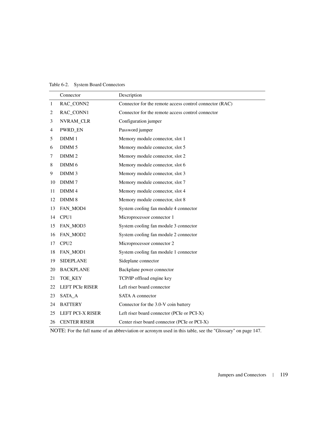
Table
| Connector | Description |
|
|
|
1 | RAC_CONN2 | Connector for the remote access control connector (RAC) |
2 | RAC_CONN1 | Connector for the remote access control connector |
3 | NVRAM_CLR | Configuration jumper |
4 | PWRD_EN | Password jumper |
5 | DIMM 1 | Memory module connector, slot 1 |
6 | DIMM 5 | Memory module connector, slot 5 |
7 | DIMM 2 | Memory module connector, slot 2 |
8 | DIMM 6 | Memory module connector, slot 6 |
9 | DIMM 3 | Memory module connector, slot 3 |
10 | DIMM 7 | Memory module connector, slot 7 |
11 | DIMM 4 | Memory module connector, slot 4 |
12 | DIMM 8 | Memory module connector, slot 8 |
13 | FAN_MOD4 | System cooling fan module 4 connector |
14 | CPU1 | Microprocessor connector 1 |
15 | FAN_MOD3 | System cooling fan module 3 connector |
16 | FAN_MOD2 | System cooling fan module 2 connector |
17 | CPU2 | Microprocessor connector 2 |
18 | FAN_MOD1 | System cooling fan module 1 connector |
19 | SIDEPLANE | Sideplane connector |
20 | BACKPLANE | Backplane power connector |
21 | TOE_KEY | TCP/IP offload engine key |
22 | LEFT PCIe RISER | Left riser board connector |
23 | SATA_A | SATA A connector |
24 | BATTERY | Connector for the |
25 | LEFT | Left riser board connector (PCIe or |
26 | CENTER RISER | Center riser board connector (PCIe or |
NOTE: For the full name of an abbreviation or acronym used in this table, see the "Glossary" on page 147.
Jumpers and Connectors
