6.1.2RxPDO mappings
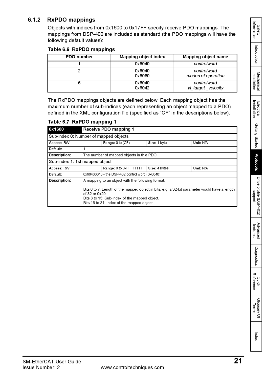
Objects with indices from 0x1600 to 0x17FF specify receive PDO mappings. The mappings from
Table 6.6 RxPDO mappings
PDO number | Mapping object index | Mapping object name |
1 | 0x6040 | controlword |
2 | 0x6040 | controlword |
| 0x6060 | modes of operation |
6 | 0x6040 | controlword |
| 0x6042 | vl_target _velocity |
The RxPDO mappings objects are defined below. Each mapping object has the maximum number of
Table 6.7 RxPDO mapping 1
0x1600 | Receive PDO mapping 1 |
|
| |
|
|
| ||
Access: RW |
| Range: 0 to (CF) | Size: 1 byte | Unit: N/A |
|
|
|
|
|
Default: | 1 |
|
|
|
|
|
| ||
Description: | The number of mapped objects in thie PDO |
| ||
|
|
| ||
Access: RW |
| Range: 0 to 0xFFFFFFFF | Size: 4 bytes | Unit: N/A |
|
|
|
|
|
Default: | 0x60400010 | - the | (0x6040) |
|
|
|
| ||
Description: | A mapping to an object with the following format: |
| ||
Bits 0 to 7: Length of the mapped object in bits, e.g. a
Bits 8 to 15:
Bits 16 to 31: Index of the mapped object.
Information | Safety |
| |
Introduction | |
|
|
Installation | Mechanical |
|
|
Installation | Electrical |
| |
Getting Started | |
| |
Protocols | |
|
|
support | Drive profile |
|
|
features | Advanced |
| |
Diagnostics | |
|
|
Reference | Quick |
|
|
Terms | Glossary |
| Of |
| |
Index | |
|
|
21 | |
Issue Number: 2 | www.controltechniques.com |