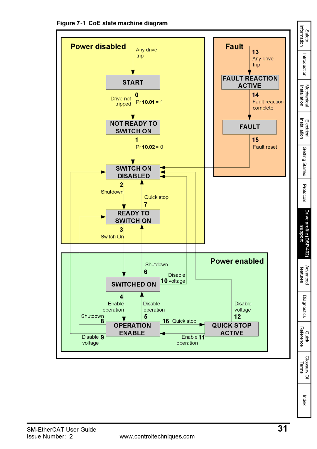
Figure 7-1 CoE state machine diagram
Power disabled | Any drive |
|
| Fault | 13 | |
|
| trip |
|
|
| |
|
|
|
|
| Any drive | |
|
|
|
|
|
| |
|
|
|
|
|
| trip |
| START |
|
| FAULT REACTION | ||
|
|
| ACTIVE | |||
|
|
|
|
| ||
| Drive not | 0 |
|
|
| 14 |
| tripped | Pr 10.01 = 1 |
|
| Fault reaction | |
|
|
|
|
|
| complete |
| NOT READY TO |
|
| FAULT | ||
| SWITCH ON |
|
| |||
|
|
|
|
| ||
|
| 1 |
|
|
| 15 |
|
| Pr 10.02 = 0 |
|
| Fault reset | |
| SWITCH ON |
|
|
|
| |
| DISABLED |
|
|
|
| |
| 2 |
|
|
|
|
|
Shutdown | Quick stop |
|
|
| ||
|
|
|
|
| ||
|
| 7 |
|
|
|
|
| READY TO |
|
|
|
| |
| SWITCH ON |
|
|
|
| |
| 3 |
|
|
|
|
|
Switch On |
|
|
|
|
| |
|
| Shutdown |
| Power enabled | ||
|
| 6 | Disable |
|
| |
| SWITCHED ON | 10 voltage |
|
| ||
| 4 |
|
|
| Disable |
|
| Enable | Disable |
|
|
| |
operation | operation |
| voltage |
| ||
Shutdown |
| 5 | 16 | Quick stop | 12 |
|
8 | OPERATION | QUICK STOP |
| |||
|
|
|
| |||
Disable 9 | ENABLE |
| Enable 11 | ACTIVE |
| |
|
|
|
|
| ||
voltage |
|
|
| operation |
|
|
Information | Safety |
| |
Introduction | |
|
|
Installation | Mechanical |
|
|
Installation | Electrical |
| |
Getting Started | |
| |
Protocols | |
|
|
support | Drive profile |
features | Advanced |
| |
Diagnostics | |
|
|
Reference | Quick |
|
|
Terms | Glossary |
| Of |
| |
Index | |
|
|
31 | |
Issue Number: 2 | www.controltechniques.com |
