5.2Quick start flowchart
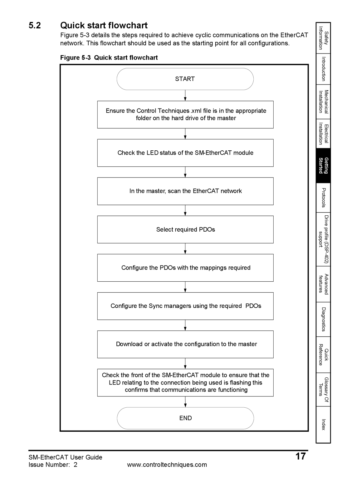
Figure 5-3 details the steps required to achieve cyclic communications on the EtherCAT network. This flowchart should be used as the starting point for all configurations.
Figure 5-3 Quick start flowchart
START
Ensure the Control Techniques .xml file is in the appropriate
folder on the hard drive of the master
Check the LED status of the
In the master, scan the EtherCAT network
Select required PDOs
Configure the PDOs with the mappings required
Configure the Sync managers using the required PDOs
Download or activate the configuration to the master
Check the front of the
END
Information | Safety |
| |
Introduction | |
|
|
Installation | Mechanical |
|
|
Installation | Electrical |
|
|
Started | Getting |
| |
Protocols | |
|
|
support | Drive profile |
|
|
features | Advanced |
| |
Diagnostics | |
|
|
Reference | Quick |
|
|
Terms | Glossary |
| Of |
| |
Index | |
|
|
17 | |
Issue Number: 2 | www.controltechniques.com |