By choosing a homing method the following behaviour is determined: The homing signal (positive limit switch, negative limit switch, home switch), the direction of actuation and where appropriate the position of the index pulse.
An encircled number in Figure
There are four sources of homing signal available: These are the negative and positive limit switches, the home switch and the index pulse from an encoder.
In the diagrams of homing sequences shown below, the encoder count increases as the axis's position moves to the right, in other words the left is the minimum position and the right is the maximum position.
7.7.1General homing definitions
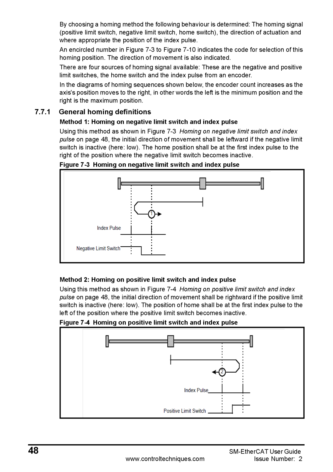
Method 1: Homing on negative limit switch and index pulse
Using this method as shown in Figure
Figure 7-3 Homing on negative limit switch and index pulse
Method 2: Homing on positive limit switch and index pulse
Using this method as shown in Figure
Figure 7-4 Homing on positive limit switch and index pulse
48 | |
www.controltechniques.com | Issue Number: 2 |