5.1.3Configuring the SM-EtherCAT module for cyclic communications
Unlike other Control Techniques fieldbus communication protocols, CoE does not require that any module parameters be changed in order to achieve communications. The baud rate of the network is fixed and the module is automatically allocated an address.
To check that the ethernet cable connected to the
In the master, scan the network ensuring that the
Decide on the input / output data you wish to send cyclically (objects and/or parameters).
Cyclic data is implemented on CoE networks by using "Process Data Objects" or PDOs. Separate data objects are used for receiving (TxPDOs - from the slave to the master) and transmitting (RxPDOs - from the master to the slave) data.
These PDOs contain the cyclic data (objects and/or parameters), the RxPDOs available are 1, 2, 6 and 22, the TxPDOs available are 1, 2, 3, 6 and 22 (for more information on these PDOs including default mappings please see section 6.1.2 RxPDO mappings on page 21 and section 6.1.3 TxPDO mappings on page 23).
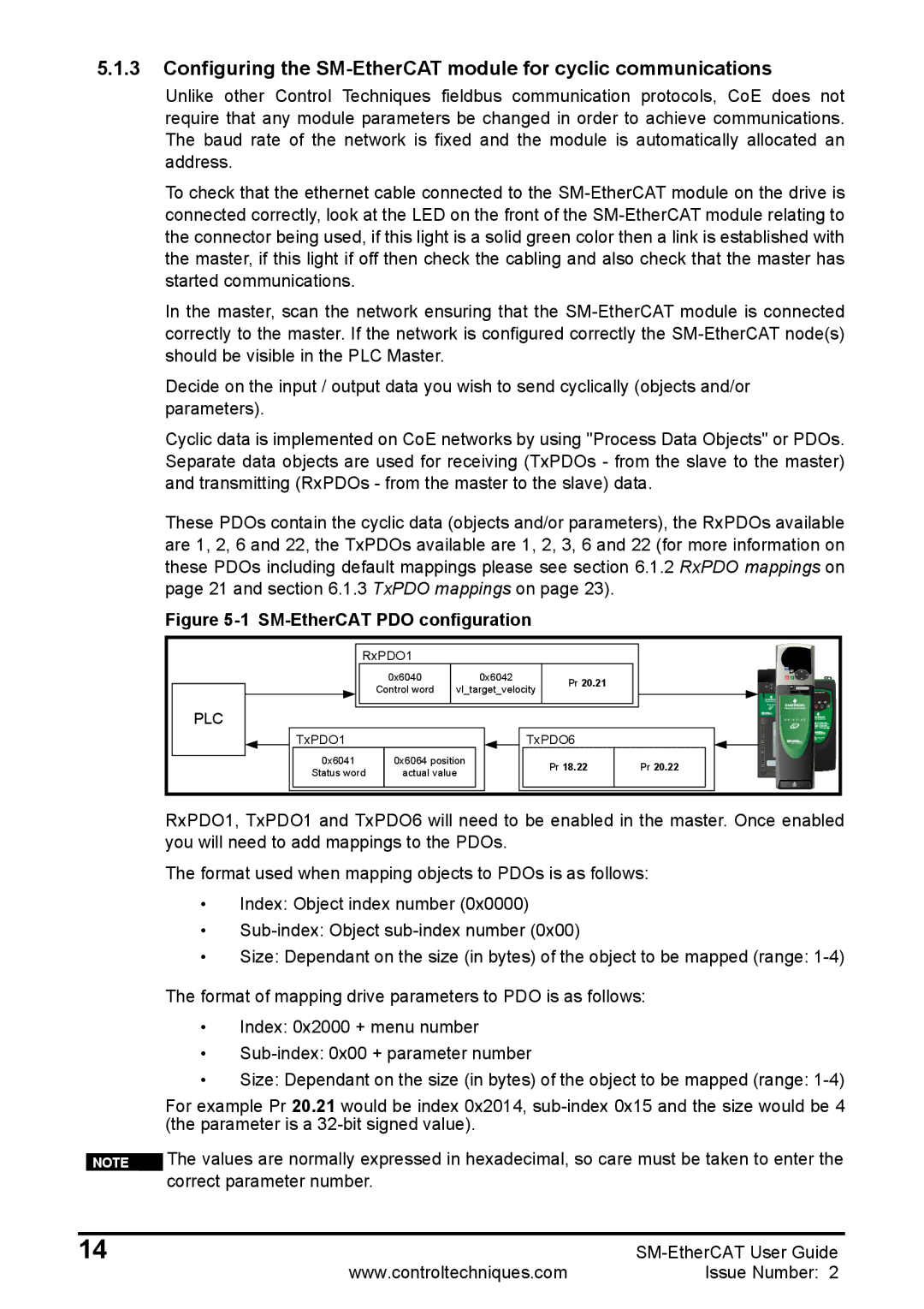
Figure 5-1 SM-EtherCAT PDO configuration
RxPDO1 |
|
|
|
|
| |
| 0x6040 |
| 0x6042 |
| Pr 20.21 |
|
| Control word | vl_target_velocity |
| |||
|
|
| ||||
PLC |
|
|
|
|
|
|
TxPDO1 |
|
|
| TxPDO6 |
| |
0x6041 | 0x6064 position |
|
| Pr 18.22 | Pr 20.22 | |
Status word | actual value |
|
| |||
|
|
|
| |||
RxPDO1, TxPDO1 and TxPDO6 will need to be enabled in the master. Once enabled you will need to add mappings to the PDOs.
The format used when mapping objects to PDOs is as follows:
•Index: Object index number (0x0000)
•
•Size: Dependant on the size (in bytes) of the object to be mapped (range:
The format of mapping drive parameters to PDO is as follows:
•Index: 0x2000 + menu number
•
•Size: Dependant on the size (in bytes) of the object to be mapped (range:
For example Pr 20.21 would be index 0x2014,
|
| The values are normally expressed in hexadecimal, so care must be taken to enter the | |
| NOTE | ||
|
| correct parameter number. |
|
|
|
|
|
14 |
| ||
|
| www.controltechniques.com | Issue Number: 2 |