MODEL 54eA | SECTION 16.0 |
| TROUBLESHOOTING |
16.14 SIMULATING TEMPERATURE
16.14.1 General.
The 54eA controller accepts either a Pt100 RTD (for pH, 499ADO, 499ATrDO,
16.14.2 Simulating temperature
To simulate the temperature input, wire a decade box to the analyzer or junction box as shown in Figure
To check the accuracy of the temperature measurement, set the resistor simulating the RTD to the values indicated in the table and note the temperature readings. The meas- ured temperature might not agree with the value in the table. During sensor calibration an offset might have been applied to make the measured temperature agree with a standard thermometer. The offset is also applied to the simulated resistance. The controller is measuring tempera- ture correctly if the difference between measured tempera- tures equals the difference between the values in the table to within ±0.1°C.
For example, start with a simulated resistance of 103.9 Ω, which corresponds to 10.0°C. Assume the offset from the sensor calibration was
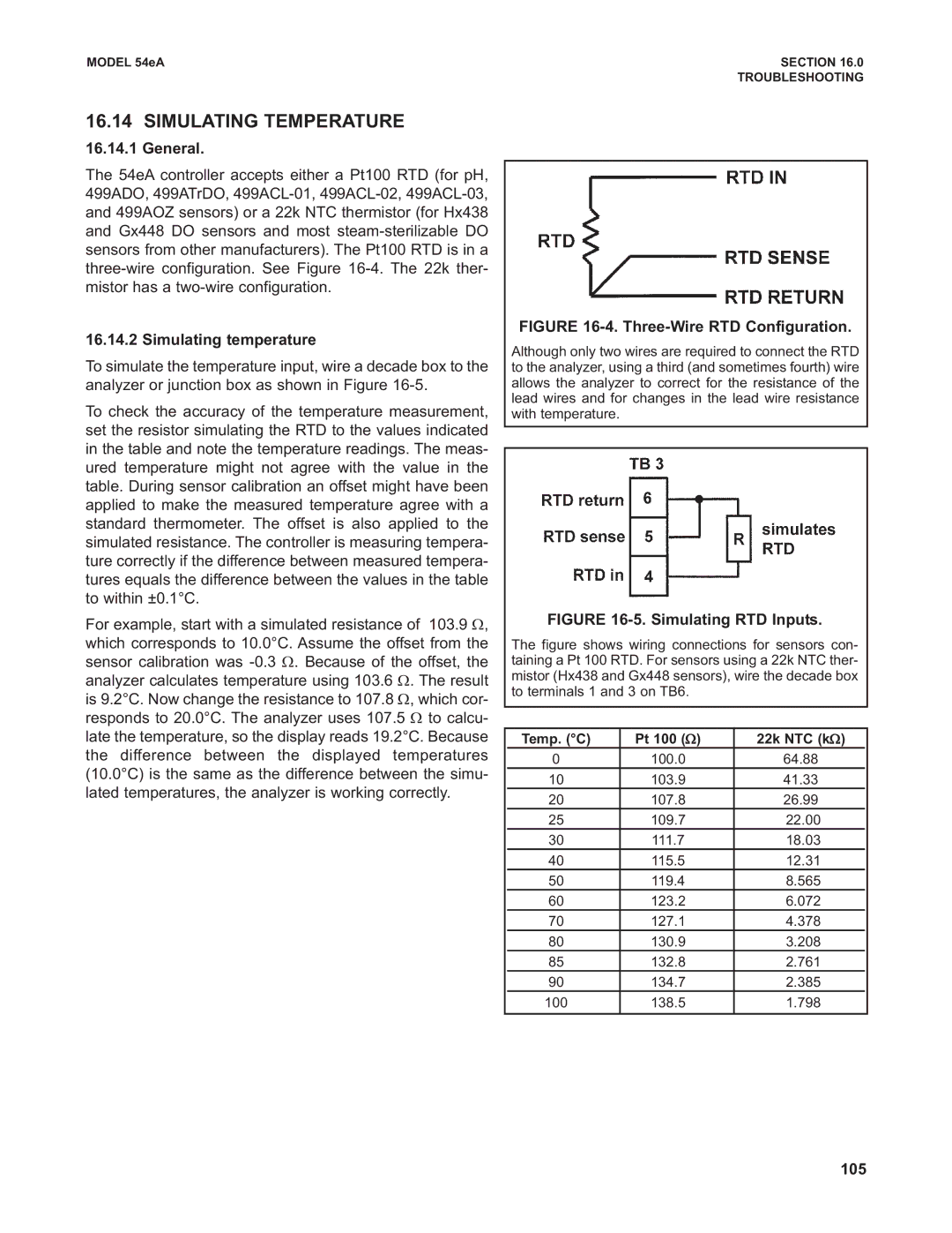
FIGURE 16-4. Three-Wire RTD Configuration.
Although only two wires are required to connect the RTD to the analyzer, using a third (and sometimes fourth) wire allows the analyzer to correct for the resistance of the lead wires and for changes in the lead wire resistance with temperature.
FIGURE 16-5. Simulating RTD Inputs.
The figure shows wiring connections for sensors con- taining a Pt 100 RTD. For sensors using a 22k NTC ther- mistor (Hx438 and Gx448 sensors), wire the decade box to terminals 1 and 3 on TB6.
| Temp. (°C) | Pt 100 (Ω) | 22k NTC (kΩ) |
|
| 0 | 100.0 | 64.88 |
|
| 10 | 103.9 | 41.33 |
|
| 20 | 107.8 | 26.99 |
|
| 25 | 109.7 | 22.00 |
|
| 30 | 111.7 | 18.03 |
|
| 40 | 115.5 | 12.31 |
|
| 50 | 119.4 | 8.565 |
|
| 60 | 123.2 | 6.072 |
|
| 70 | 127.1 | 4.378 |
|
| 80 | 130.9 | 3.208 |
|
| 85 | 132.8 | 2.761 |
|
| 90 | 134.7 | 2.385 |
|
100 | 138.5 | 1.798 |
| |
|
|
|
|
|