Emerson Process Management 53eA instruction manual 4054eA01

Models: 53eA

1 116
Download 116 pages 57.39 Kb
Page 17
Image 17

MODEL 54eA

SECTION 3.0


WIRING

3.3.3 Wiring 499ACL-01 (free chlorine) sensors and pH sensors for automatic pH correction.

If free chlorine is being measured using the 499ACL-01 sensor and the pH of the liquid varies more than 0.2 pH unit, a continuous correction for pH must be applied to the chlorine reading. Therefore, a pH sensor must also be wired to the 54eA controller. This section gives wiring diagrams for the pH sensors typically used.

When using the 499ACL-01 sensor (free chlorine) with a pH sensor, use the RTD in the pH sensor for meas- uring temperature. DO NOT use the RTD in the free chlorine sensor.

The pH sensor RTD is needed for temperature measurement during buffer calibration. During normal operation, the RTD in the pH sensor also provides the temperature measurement required for the free chlorine membrane permeability correction.

NOTE

When wiring a pH and a 400ACL-01 amperometric sensor to the controller, connect the anode and reference terminals (TB3-1 and TB5-1) with the 10MΩ jumper (PN 23980-00) provided with the analyzer.

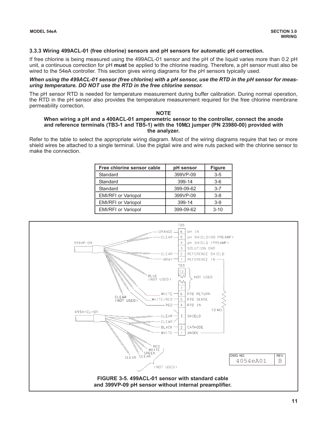
Refer to the table to select the appropriate wiring diagram. Most of the wiring diagrams require that two or more shield wires be attached to a single terminal. Use the pigtail wire and wire nuts packed with the chlorine sensor to make the connection.


Free chlorine sensor cable

pH sensor

Figure


Standard

399VP-09

3-5


Standard

399-14

3-6


Standard

399-09-62

3-7


EMI/RFI or Variopol

399VP-09

3-8


EMI/RFI or Variopol

399-14

3-9


EMI/RFI or Variopol

399-09-62

3-10


DWG. NO.

4054eA01

REV.

B

FIGURE 3-5. 499ACL-01 sensor with standard cable and 399VP-09 pH sensor without internal preamplifier.

11

Page 17
Image 17
Emerson Process Management 53eA instruction manual 4054eA01