Printer
Rev. F
Ii Contents
Copyright 2000, Output Technology Corporation
Trademarks
Important Safety Precautions
Page
Supplies and Services
FCC Compliance Statement
EPA Energy Star Printers Partner
DOC Compliance Statement
Certificate of MANUFACTURER/IMPORTER
Contents
Configuration
Operations
Configuration
Maintenance
Troubleshooting
Control Commands-An Introduction
Universal Control Commands
Epson FX-100 Control Commands
IBM Proprinter XL Control Commands
DEC LA210 Control Commands
Appendix a Specifications
Appendix B Serial Interface
Appendix C Parallel Interface
Appendix D Character Sets
Xx Contents
Appendix E Barcodes
Glossary Index
Xxii Contents
Basic Physical Features
Basics
Basics
Operator Access
Close Operator Access Door Turn on printer
Basic Startup and Printing
Check Print Quality
Basic Controls and Indicators
Power ON/OFF Switch
Switch Panel
Paper
NLQ Power
Page
Power-Up Hot Keys
Combination Keys
Feed and Line FEED, turn
On-Line Hot Keys
Feed and Line Feed at
Page
Page
Power Receptacle
Basic Connections
Parallel Interface
Interface Connectors
Serial Parallel
Basic Beeps
Serial Interface
Basics
Operators Guide
Basics
Common Operations
Loading Paper
Page
Paper Specifications
Operations
Operators Guide Left Tractor
Adjusting the Printhead GAP
JB0-AJ1
Running a Self Test
Setting TOP of Form
Paper Position Keys Paper Movement
JB0-AK1
Switching NLQ and Draft
Emulations and Printer Drivers
Changing Emulations
Then, press YES. The printer prints out
Printing the Active Character SET
Respond by pressing YES. The printer prints out
JB0-AM
JB0-AN
JB0-AO
NUL
Operators Guide Hexadecimal-To-Decimal Conversion
What Is a Character Set?
Configuration
Page
Configuration Menu
Accessing the Configuration Menu
Navigating the Configuration Menu
Exiting the Configuration Menu
Press on Line along with Line Feed
Adjusting the PRINTER’S Performance
Page
Configuration MAP
Configuration MAP
Barcode Options
Non-Default List?
Help
Status Print?
Menu Tree?
Print All Options?
Diagnostic Codes?
Hot Key List?
Print Active Character Set?
Print Data Byte Map?
ROM
Source Character Library Type of Character
RAM
Interface Options
Active Interface
Serial Options
Protocol
DTR ON/X-OFF ETX/ACK
DTR Polarity
OFF When Off Line
Robust X-ON
Baud
Data Bits
Parity
Input Buffer Size
Stop Bits
Page
Print Style
Near Letter Quality
Bi-Directional Graphics / NLQ
Bold Print
Italics
Subscript/Superscript
Char/Inch
Forms Options
Slash Zero
Lines/Inch
Form Length
Skip Perf
LF on CR
CR on LF
Paper Jam Detect
Paper Speed
Emulation
Character Options
Epson Character Options
Epson Control Code Map
Epson Character Map
Epson IBM #1 Code
IBM Character Options
Epson IBM #2 Code
IBM Control Code Map
IBM #1 Code
IBM #2 Code
DEC Character Options
DEC Character Set
Character Maps G0 through G3
Overlay Characters
OCR a OCR B
Barcode Strike
Barcode Options
Barcode Density
System Options
Factory Reset
Lock Character Set and Emulation
Initialize Sensitivity
Vertical Alignment
Maintenance
Static Electricity
Cleaning
Interior Surfaces
Lubrication
Exterior Surfaces
Changing Ribbon Cartridge
Page
Operators Guide Installing Ribbon Cartridge Left-End View
Page
Clean Way To Re-Attach a Ribbon Guide
Changing Forms Compressor
Operators Guide Forms Compressor Left End
Maintenance Installing a Forms Compressor
Changing Fuses
DA0-E DA0-F
Vertical Image Alignment
Page
Proper Vertical Alignment
Improper Vertical Alignment
Maintenance
Troubleshooting
Troubleshooting
Page
Page
Troubleshooting Chart
Problem Probable Cause Solution BEEPs
Troubleshooting Chart
Print Quality
Print Quality Problem Probable Cause Solution
Paper Problems Positioning, Feeding, Paper Out, Jamming
Consider using the bottom feed path
Switch Panel
Problem Probable Cause Solution Communications
Printhead Performance
Troubleshooting Aids
POWER-UP Sequence Test
HEX Dump Mode
On Line
JB0-AL
Control Commands An Introduction
Communication Basics
Identifying Data Bytes
Binary Number System
Decimal Number System
Hexadecimal Number System
Page
Printable Characters
Three Categories of Data Bytes
Control Codes
Sending Control Codes and Control Commands
Control Commands
Using Batch Files to Send Commands
Using Basic to Send Commands
Copy CON 12PITCH.BAT Echo ¢!A PRN
Where the prefix &H is used to denote hexadecimal numbers
Sending Commands from the DOS Command Line
Using Control KEY Sequences to Send Commands
Ascii
Typographic Conventions
Format
Parameters
Data Byte Values of Command Parameters
Universal, Epson, and IBM Control Commands
DEC Control Commands
Zeros and Ones
Universal Control Commands
Index of Universal Control Commands
Alphabetical Summary of Universal Control Commands
Command Function
Download Characters
Graphics
Form Length
SOH a z C Length of Form in Millimeters
Emulation Mode
SOH a z a Select Emulation and Reset Printer
Miscellaneous
SOH a z Reset to Power Up Settings
SOH a z Y Inch Line Spacing
Bit Setting
Operator’s Guide
SOH a z Set Pitch and Strike
Pitch Single Double Bold Extra
Universal Control Commands 18.2 17.14 16.67 15.0 12.0 10.0
SOH a z L Enable/Disable Barcode Printing
Barcodes
Operator’s Guide SOH a z T Select Print Quality
SOH a z M Set Barcode Parameters
Data Byte Action Map
Mapping Characters
Control Code Map
Operator’s Guide
ABO-N1
AB0-O
SOH a z % Select Character Source and Library
Character Source Library
SOH a z B Map Characters
Example
Download Characters
Designing Download Characters
Character Design Matrix
Designing Ascending and Descending Characters
Extended Characters
Extended Characters
Print Quality
Print Quality, NLQ Download Character
Page
Storing Download Characters
Printing Downloaded Characters
162 Universal Control Commands SOH a z Download Characters
Aa Bit Setting
Setting
Page
Page
Example
Example
AB0-Y1
AB0-ZA
Lprint CHR$1Az&CHR$1CHR$48CHR$48CHR$0CHR$1 for X = 1 to
AB0-AA1
Graphics
SOH a z Universal Graphics
Pitch Maximum Dot Density Columns Per Line
D1d2 C1c2
Cell Dot Values Column 128 19 =
Read D Lprint CHR$D Next
Universal Control Commands
Epson FX-100 Control Commands
Index of Control Codes and Commands
184
195
Inch
Cancel Data in Print Buffer
Cancel MSB Control
Miscellaneous Printer Initialization
199
Cancel Elite Pitch
Enlarged Pitch SO or ESC SO 222 Cancel Enlarged Pitch
Cancel Double Strike
Emphasized Mode Bold Strike on
Command Function
Alphabetical Summary
Unavailable Epson FX-100 Control Commands
Epson Control Equivalent Universal Control Sequence Command
ESC EM
ESC SP
Character Sets
Character Map
Ascii ESC
Control Codes/Printable Characters
ESC C
ESC C NUL
ESC K
Cell Dot Values Column 128 19 =
Lprint CHR$27KCHR$8CHR$0 For I = 1 to
Single Density Double Density
Operator’s Guide ESC L or ESC Y Double-Density Graphics
Lprint CHR$255 Next J END
ESC Z
Dots/In Where x of dx =
194 Epson FX-100 Control Commands
Maximum No. of d-bytes
ESC
Line Spacing
ESC Ø
196 Epson FX-100 Control Commands ESC 3 or ESC J Inch
Margins
ESC N
ESC O
ESC @
BEL
Epson FX-100 Control Commands Backspace
Can
DEL
ESC s Half-Speed Printing
DC1
DC3
ESC =
ESC #
Print Direction
Unidirectional/Bidirectional Printing
Print Style
Pitch Strike
Current Pitch After SI or ESC SI
DC2
New Pitch Previous After SI or ESC Ptich
ESC M
Current Pitch After ESC M
ESC P
Current Pitch After ESC P
Current Pitch After SO or ESC SO
DC4
Pitch Set with SO or ESC SO After DC4
Set/Cancel Enlarged Pitch
Current After ESC W Previous Pitch
ESC Set/Cancel NLQ
ESC H
ESC G
ESC E
Set/Cancel Underline
ESC F
ESC S
ESC T
Tabs
ESC D
Horizontal Tab
ESC B
ESC b Set Vertical Tab Channel
ESC
Epson FX-100 Control Commands
IBM Proprinter Control Commands
Character Sets Select IBM Character Set #2
239
Select IBM Character Set #1
240
Enlarged Pitch SO or ESC SO 258 Cancel Enlarged Pitch
Set/Cancel Enlarged Pitch ESC W n 260 Set 12 Pitch
Miscellaneous Carriage Return 251 Bell
253
Tabs
ESC R
ESC \
Unavailable IBM Proprinter Control Commands
ESC \
Print One Character From All Character Set
ESC C
IBM Proprinter Control Commands
Graphics
Single Density Double Density
Example
234
Start Text Line Spacing
236 IBM Proprinter Control Commands ESC 3 or ESC J Inch
Margins
238
Miscellaneous
IBM Proprinter Control Commands Linefeed
Set Top of Form
ESC Q Deselect Printer
Print Direction
Lprint CHR$27CHR$58 Lprint Now printing in 12 cpi
Previous New Pitch After After SI or
Pitch After ESC
ESC W
Pitch Set with SO or After DC4
ESC SO
Current After ESC Previous After ESC W Pitch
Current Pitch After ESC
250 IBM Proprinter Control Commands
Lprint CHR$27-CHR$0 Lprint Underline function is off
ESC S
Tabs
Example
REM SET Vertical Tabs to Lines 5
IBM Proprinter Control Commands
DEC LA210 Control Commands
Map G3 into Upper Data Bytes
Map G2 into Upper Data Bytes
288
Cancel
Enable C1 Control Codes
Disable C1 Control Codes
299
Paper Motion
Pitch
Special Printhead Movement
Print Direction
Tabs Set Horizontal Tab ESC H or 316 At Current Column
318
Horizontal Tab 318 Vertical Tab Set
Set Vertical Tab at ESC J or 319 Current Line
CSI
CommandFunctionPage
Unsupported DEC Commands
Printer VS DEC LA210 Printer
EOT
DLE
NAK
SYN
Character Pitch Differences
Graphics Density Differences
Character Pitch
Control LA210 Printer Sequence
Aspect Dots/inch Overlap Ratio Dots/line Inches/line
DEC LA210 Emulation Graphics Densities
DEC LA210 Emulation Printer Graphics Densities
Character Maps
AB0-AJ
Using the Configuration Menu to Select Character Maps
Using Control Commands to Select Character Maps
ESC n Select G0
ESC * n Select G2
Operators Guide ESC n Select G1
ESC + n Select G3
ESC n Map G2 into Lower Data Bytes
Map G2 into Upper Data Bytes default
Operators Guide ESC o Map G3 into Lower Data Bytes
ESC N or SS2 Print Next Character from G2
ESC O or SS3 Print Next Character from G3
Lines PER Inch
ESC n z Set Line Spacing
Lines Per Inch
Decimal Hexadecimal
ESC n s or ESC n Ø s Left Margin
Margins
ESC n s or ESC Ø n s Right Margin
ESC n1 n2 s Left and Right Margin
ESC n r Top Margin
282 DEC LA210 Control Commands ESC n r Bottom Margin
ESC n1 n2 r Top and Bottom Margin
Operators Guide ESC n1 n2 s Set Print Area
ESC 2 Ø h Enable Linefeed/Newline
ESC 2 Ø l Disable Linefeed/Newline
Operators Guide ESC ? 4 Ø h Enable Carriage Return/Newline
ESC ? 4 Ø l Disable Carriage Return/Newline
ESC ? 7 h Enable Auto Wraparound
ESC ? Disable Auto Wraparound
ESC Ø t No Form Mode
Cancel
C0 Control Codes
C1 Control Codes
Operators Guide ESC P 1 Define Answer Back Message
ENQ
290 DEC LA210 Control Commands DCS 1 Device Control String
ESC \ or ST String Terminator
ESC P n q d1..dx Graphics
Graphics Densities
Dots Aspect Inches Overlap Ratio Line
Page
Processed without Exiting Graphics mode Ignored
NUL EOT ENQ
Lprint CHR$27P2q`QKKQ`CHR$27\
ESC D or IND Index
Paper Motion
ESC E or NEL Linefeed with Carriage Return Next Line
Operators Guide ESC K or PLD Advance Paper 1/12 Inch
ESC n d Advance to Line n
ESC n e Advance n Lines
Operators Guide
ESC n w Select Pitch
Ascii
ESC ? 2 9 h Select Font Pitches
ESC Ø z or ESC 1 z Draft Quality Printing
ESC 2 z Near Letter Quality Printing
Operators Guide ESC 4 m Enable Underline
ESC 2 4 m Disable Underline
ESC 2 m Enable Underline
ESC Ø m Disable Underline
ESC n ` Set Active Column to Column n
Special Printhead Movement
ESC n a Advance n Columns
ESC ? 4 1 h Unidirectional Printing
ESC ? 4 1 l Bidirectional Printing
ESC H or ESC Set Horizontal Tab at Current Column
ESC g or ESC Ø g Clear Horizontal Tab at Current Column ‡
ESC n1 n2 ...n16 u Set Multiple Horizontal Tabs §
Operators Guide ESC n u Set Horizontal Tab at Column n4
ESC 2 or ESC 2 g or ESC 3 g Clear All Horizontal Tabs §
HTS
VTS
Ascii
N15 Control
Appendix a Specifications
Characteristics
Throughput
Characteristics
Paper Feed
Width Bond Weight Single-Part Paper
Emulations
Ascii
Human-Readable Fonts Text Characters
Human-Readable Fonts
Graphics
Safety Features
Reliability
Physical
Requirements
Electrical
Environmental
Interface
Paper
Size and Print Area Symbol Description Specification
Operators Guide A-15
Appendix A-Specifications
Operators Guide A-17
Label blank Base Label paper With label No label Blank blank
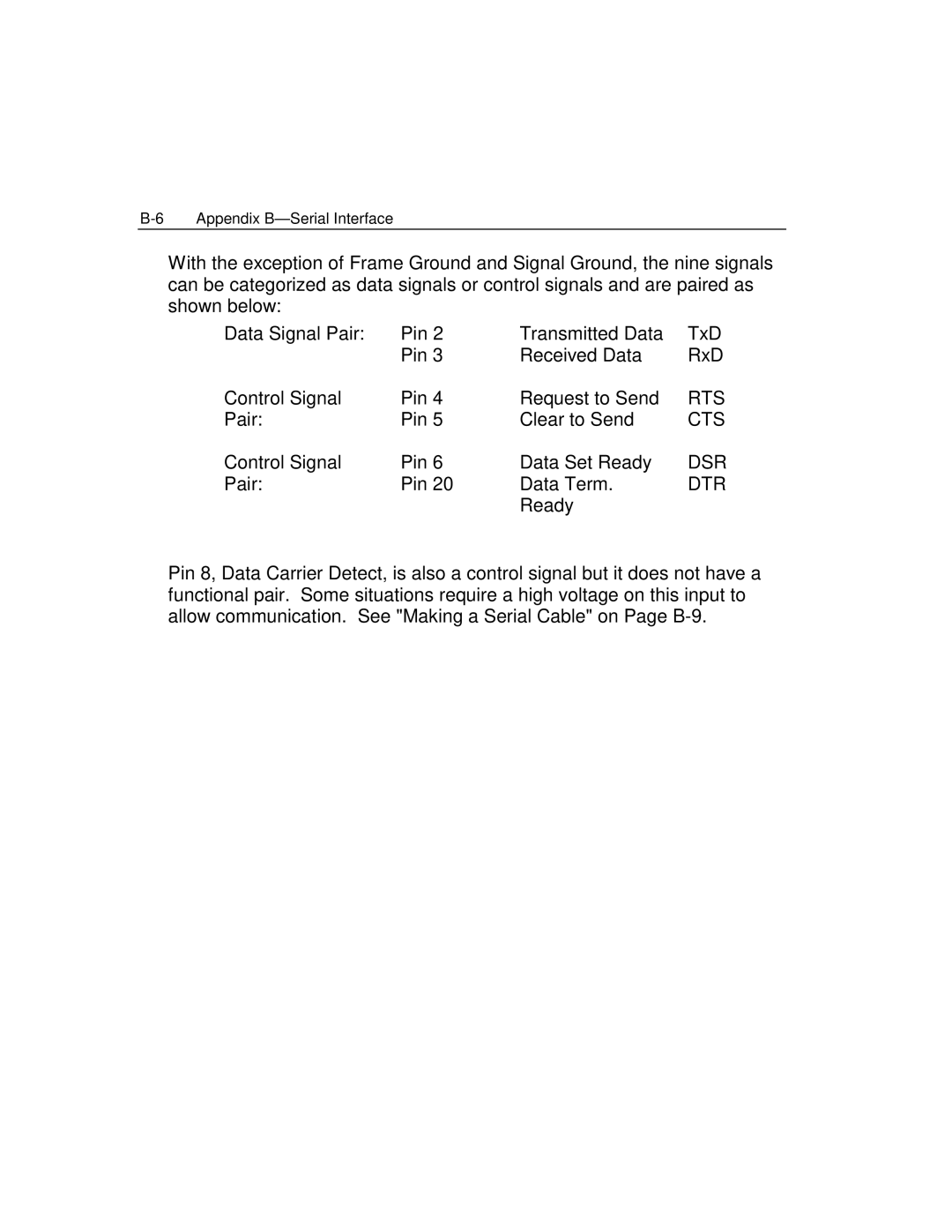
Appendix B Serial Interface
Serial Interface Basics
JB0-BL
DTE Device DCE Device Pin # Signal Abbreviation
EIA RS-232-C Pin Assignments
DTE Device DCE Device Pin # Signal Abbreviation
Common RS-232-C
DTE/DCE Device Chart
DTE Device
Pair Pin Clear to Send
Pin # Signal Name Abbr Comment
Serial Interface PIN-OUTS for Printer
Making a Serial Cable
Operators Guide Printer To DCE Device Wiring Diagram
Page
Connection Examples
IBM PC to Printer
IBM PC/AT* to Printer
AB0-AP
Software Handshaking
Handshaking
ON/X-OFF ETX/ACK
ETX/ACK
Hardware Handshaking
Busy Inverse DTR
If YOU Cannot Make IT Work
Page
Interface Circuits
Appendix B-Serial Interface Version
Appendix C Parallel Interface
Parallel Interface Basics
Synchronization
Data
Handshaking
Parallel Interface PIN-OUTS for Printer
Parallel Interface Pin Assignments
STROBE* RET
GND
Parallel Interface Timing
JB0-BQ2
Appendix D Character Sets
American Standard Code for Information Interchange
Page
Terminology
Main Character Library
Standard Ascii Character SET
DEL
128 144 160 176 192 208 224 240
Process of Creating Character Sets
JB0-BG1
JB0-BH1
Control Code MAP
Epson Control Code MAP
IBM Control Code Maps
Operators Guide D-13
DEC 7-BIT C0 Control Code MAP
DEC 8-BIT Control Code Maps
Operators Guide D-15
Character MAP
Configuration Menu Character Maps
Epson NATIONAL-USE Character MAP
7 -8 -9 -A
Operators Guide D-19
Epson Hebrew Character MAP
Operators Guide D-21
IBM Code page 437 U.S
Operators Guide D-23
IBM #2 Code page 437 Hebrew
Operators Guide D-25
IBM Code page 850 Multilingual
Operators Guide D-27
IBM Code page 860 Portugal
Operators Guide D-29
DEC NATIONAL-USE Character MAP
1-/9 6 -7 -8 -9 -A
DEC Multilingual Character MAP
DEC Hebrew Character MAP
DEC VT100 Line Draw Character MAP
OCR a Overlay Character MAP
OCR B Overlay Character MAP
Character Substitutions for Epson NATIONAL-USE Character MAP
Character Substitutions for DEC NATIONAL-USE Character MAP
Character SET
Epson Enhanced Character Sets
IBM ALL Character Character SET
IBM #2 Multilingual Character SET
Operators Guide D-41
Epson ESC I Printable Character Overlay
Operators Guide D-43
Epson ESC 6 Printable Character Expansion Overlay
Operators Guide D-45
Epson Standard Code page Character SET
Operators Guide D-47
IBM ALL Character Overlay
Operators Guide D-49
IBM #2 ALL Character Multilingual Character SET
Operators Guide D-51
Appendix D-Character Sets
Appendix E Barcodes
Printing Barcodes
Lprint CHR$1 AzLØ
Barcode Format Command
Ascii SOH
P1 Barcode Symbology
P1 Through P8
P2 Barcode Height
P3 Human Readable Line
P4 Narrow Bar Width
P5 Wide Bar Width
P7 Wide Space Width
P6 Narrow Space Width
P8 Intercharacter Gap
Start Barcode Command
Barcode Format Command Example
Control
Decimal 122
Barcode Data
Valid Characters
Code
C D E F G H I J K L M N O P Q R S T U V W X Y Z
Interleaved 2
Entering Barcode Data
Quiet Zone
Spaces
Postnet Placement on AN Envelope
Lprintlprintlprintlprint
Check Digits
Number System Characters and Country Flags
Start CHARACTERS, Stop CHARACTERS, and Guard Bars
Summary of Required Barcode Data
END Barcode Command
Examples
REM Format UPC-A Barcode Symbol
ESC P1P2P3P4P5P6P7P8
Alternate Commands
ESC
Parameter Options Setting
P4 Through P8 Integrity
Parameter Formula Principle
Page
Glossary
Page
Page
Page
Page
Only Memory
Index
Index
Operators Guide