Page
Fujitsu DL3700 Pro/3800 Pro
Page
Bescheinigung des Herstellers/Importeurs
CE Declaration
Energy Saving
DOT Matrix Printer
Manufacturers Declaration of Conformity
Trademark Acknowledgement
Options
Printer Models
Vii
Organization
Viii
Indicated as follows
Users
Table of Contents
General Tips Multipart Forms Envelopes
Switching to Single Sheets Switching to Continuous Forms
DPL24C Plus Organization
Using Setup Mode
Xii
Installing the Cut Sheet Feeder Installing the Color Kit
GL-1
Factory Default Settings
Compatible Mode Nibble Mode Data Transmission Timing
Serial Options Cable Wiring Serial Protocols
Xiv
Control panel
Quick Reference
Quick Reference
Printer Operations Normal Mode
Dot matrix printer
Features
Introduction
Cut sheet feeder
Options
Introduction
Location
Selecting a Good
Setting UP
Checking items received
Unpacking the Printer
Removing the shipping restraint cardboard
Checking Options and Supplies
Installing the cut sheet stand
Installing the Cut Sheet Stand
Preparing to install the ribbon
Preparing the ribbon cartridge
Installing the ribbon cartridge
Getting Acquainted
With Your Printer
Printer components front and right
Connecting the Power
Printer components rear
Cord
Connecting the power cord
Testing the Printer
Offline
Loading a sheet of paper
Printing the Self-Test
Starting the self-test
Sample self-test
Setting UP
Demo pattern
Selecting a Parallel Interface Cable
Opening the shutter
Connecting the interface cable
For Experienced Users
Selecting AN Emulation
Turn the printer on and load a sheet of paper
Enter setup mode
Initial printout in setup mode
Select an emulation
Select the MENU1 function
Exit MENU1
Exit setup mode to save the emulation
Setting UP
Using MS-DOS to Specify Serial Interface Settings
Mode LPT1=COM1
Setting UP
Selecting Paper
Paper Handling
Printer levers and buttons
Paper Handling
Overview of Paper
Operations
Tear OFF
Levers and Buttons Used for Paper Handling
Lever/Button Purpose Action
LF/FF
Adjusting for Paper
Adjusting the paper thickness lever
Thickness
Move the lever one setting higher
Paper Thickness Lever Settings
Using Single Sheets
Number of Copies Setting *2 Including the Original *1
Preparing to load a sheet of paper
Adjusting the left margin
Load
Loading Paper in the Cut Sheet Feeder Option
Preparing the cut sheet feeder ASF300
Preparing the cut sheet feeder ASF100
Adjusting the left margin
Loading the cut sheet feeder ASF300
Loading the cut sheet feeder ASF100
Forms
Using Continuous
Positioning the Paper Stack
Good placement
Bad placement
Placement of continuous forms
Preparing to load continuous forms paper
Loading Continuous Forms Push Tractor and Rear Feed
Positioning the tractors Adjusting the left margin
Lowering the cut sheet stand
Adjusting paper tension
Loading Continuous Forms Pull Tractor and Bottom Feed
Removing the bail roller unit
Removing the tractor unit
Installing the tractor unit for pull-tractor feed
Opening the two holders
Passing continuous forms paper from under the printer
Setting continuous forms paper on the tractors
Unloading Continuous Forms
Tearing off continuous forms
Feeding and Positioning Paper
Micro Feed
Failure to retract the forms paper will cause paper jams
Switching to Single Sheets
General Tips
Tips on Paper Handling
Labels
Paper Handling
Printing
Using Commercial Software
Printing
Printer control panel
Selecting MENU1 or MENU2
MENU1 MENU2
MENU1 and MENU2 Settings
Menu Font
Prestg
Draft
Hidrft
Locking the selected resident font
Starting or Stopping Printing
Stopping Printing
Printing the remaining lines on a
Continuing printing after supplying paper
Removing Single Sheets
Buffer
Clearing the Print
Using Setup Mode
Entering Setup Mode
Using Setup Mode
Entering setup mode
Function Purpose
Setup Mode Functions
HEX-DUMP
Default
List
SELF-TST
Select the MENU2 function
Load continuous forms paper Enter setup mode
Almnt
Summary of setup mode
Select the current print quality
Exit setup mode, saving the new font and pitch
Select the current emulation
Change the font to Prestige Elite
Setup Mode
Select the List function
Use the printer tear-off feature Tear OFF button
Printing a List
Selected Options
Printout of factory defaults using List
Deciding Which Options
To Change
Required Options
See the section Changing Print Position
Adjustment Options later in this
See the section Changing Configuration
See the section Changing Hardware
Using Setup Mode
MENU1 and MENU2 Items and Options
Report
Font TIMLS-N TIMLS-B TIMLS-I DOWNLD#
Quality
Letter
Lpi Lpi double spacing
CHAR-H
Attrib
None Italics Condnsd Shadow Bold
Yellow
Color
Autosel
Black
## Line
LFT-END
## Colm
TOP-MRG
Swedish
Languge
USA
German
POLSH-T
Languge Slov
SLOV-T
Polish
DANISH1
Languge French
Italian
Spanish
Graphic
CHR-SET
SET
Italic
Zerofnt
Enable
Disable
Width
OVR-PRT
LF-CODE LF only
LF & CR
Rghtend Wrap
Select the MENU1 or MENU2 function
Exit MENU1 or MENU2
Options Description Items
Indicator lights red, regardless
PPR-OUT setting
Hardwre Items and Options
Print buffer Download buffer
Cannot accept any download font
0BYTE option is recommended
Only for graphics application
With 128KB selected, the printer
DSR Ignore
XON/XOF
DTR
REV-CHL
Select an option for the selected item
Select the Hardwre function
Changing Print Position Adjustment Options
Options Description
Adjust Items and Options
CNT-LFT
CUT-LFT
CUT-ADJ
Select the Adjust function
Exit the Adjust function
Select an option from 1/6IN to 66/6IN
Check the top-of-form setting
Changing Configuration Options
Config Items and Options
Exit setup mode, saving the top-of-form setting
Length setting does not match
Positioning will fail if
Actual perforation spacing
Decode
Cutload
Button
Loadtim
Offline
Setup
Areacnt
ON-LOAD
CONT-PE
Tractor
Edge
Select the Config function
Exit the Config function
Select an option
Select the SAVE/END function
Print the Function menu
Resetting Power-On Defaults
Resetting Defaults
Using the Diagnostic
Select the Default function
Functions
Printing the Self-Test
Select the SELF-TST function
Examine the self-test
Exit the SELF-TST function
Print the hex dump
Select the HEX-DUMP function
Exit the HEX-DUMP function
Sample hex dump
Checking Vertical Print Alignment V-ALMNT
Select the V-ALMNT function
Adjust the vertical print alignment at letter quality speed
Adjust the vertical print alignment at correspondence speed
Adjust the vertical print alignment at draft speed
Exit the V-ALMNT function
Setup Mode Reference
To exit the V-ALMNT function, you must exit setup mode
Correct vertical print alignment
Setup Mode Functions Items & Options Online
Setup
Differences in IBM Proprinter XL24E Emulation
Japan
Online Setup Mode
Cleaning and Vacuuming the Printer
Cleaning
Printer interior
Maintenance
Rubber to harden
Replacing the Ribbon
Removing the ribbon cartridge
Paper thickness lever
Preparing the new ribbon cartridge
Installing the new ribbon cartridge
Replacing the print head
Maintenance
Print Quality Problems
Solving Problems
Ing an Emulation in Chapter
TROUBLE-SHOOTING
Print Quality Problems and Solutions
Problem Solution
Using the Diagnostic Functions in Chapter
Section Changing MENU1 and MENU2
Changing MENU1 and MENU2 Options
Paper Handling Problems and Solutions
TROUBLE-SHOOTING
Tips for clearing a jammed sheet from the printer
Common cause of abnormal paper feeding
Operating Problems and Solutions
Ing Hardware Options in Chapter
PRESTG12
Error Font indicators lit
Printer Failures
COUR10
Diagnostic Functions Getting Help
TROUBLE-SHOOTING
Single bin cut sheet feeder
Installing the CUT Sheet Feeder
Installing Options
Installing the Color KIT
Color kit ribbon shift unit
Seven colors are printed by command
Installing Options
Supplies Options
Supplies Order Number
Option Order Number Description
Supplies and Options
Physical Specifications
Functional Specifications
Printer and Paper Specifications
Number of copies
Command sets emulations
Paper thickness
Paper length
Performance Specifications
Certification
Line feed speed
Form feed speed
Ribbon life
Print area for single sheets
Paper Specifications
Print area for continuous forms
Type of Paper Number of Parts Thickness
Do not use in high humidity environments
Printer and Paper Specifications
Command Sets
Command Sets DPL24C Plus
Function Command Print Mode Control
Fujitsu DPL24C Plus
Function Command
Command Sets
Horizontal Control
ESC M
ESC P
ESC LF
Vertical Control
ESC O
Function Command Tabulation
NUL
Formatting
Character Set Control
Color Selection
Bit Print quality
Word Processing
Font Selection and Downloading
Bit Selection of font
= 0 = 1
Quality Spacing Pitch Point Typeface
Bit Font number selection Remarks
Bit Font quality selection
Bar Code Printing
Function Command Bit Image Graphics
Cut Sheet Feeder Control
Initialize Printer
Ascii
Selectable options in setup mode Command
ESC G ESC H
NONE, ITALICS, Condnsd
SHADOW, Bold
ESC E ESC F
SKIP, NO-SKIP ESC N ESC O
DC3 ENABLE, Disable
ESC7
ESC6
IBM Proprinter XL24E Emulation
DC4
Height Spacing
Command Sets IBM XL24E
DC2
ESC T
ESC B NUL
ESC D NUL
Function Command Color Selection
Code page ID
ESC Q #
Function Command Downloading
Miscellaneous
BEL
Command Sets ESC/P2
Epson ESC/P2
Emulation
Space Backspace Carriage return Set elite pitch
ESC D
× 256/360*1 inch
Function Command Color Selection
DEL
≤ character codes ≤
Command Sets ESC/P2
Graphics type m graphics ESC * m n1 n2
Command Sets ESC/P2
Parallel Interface
Unidirectional forward channel mode or conventional mode
Tion
Compatible Mode
Pin Return Signal Direc Description Pin No
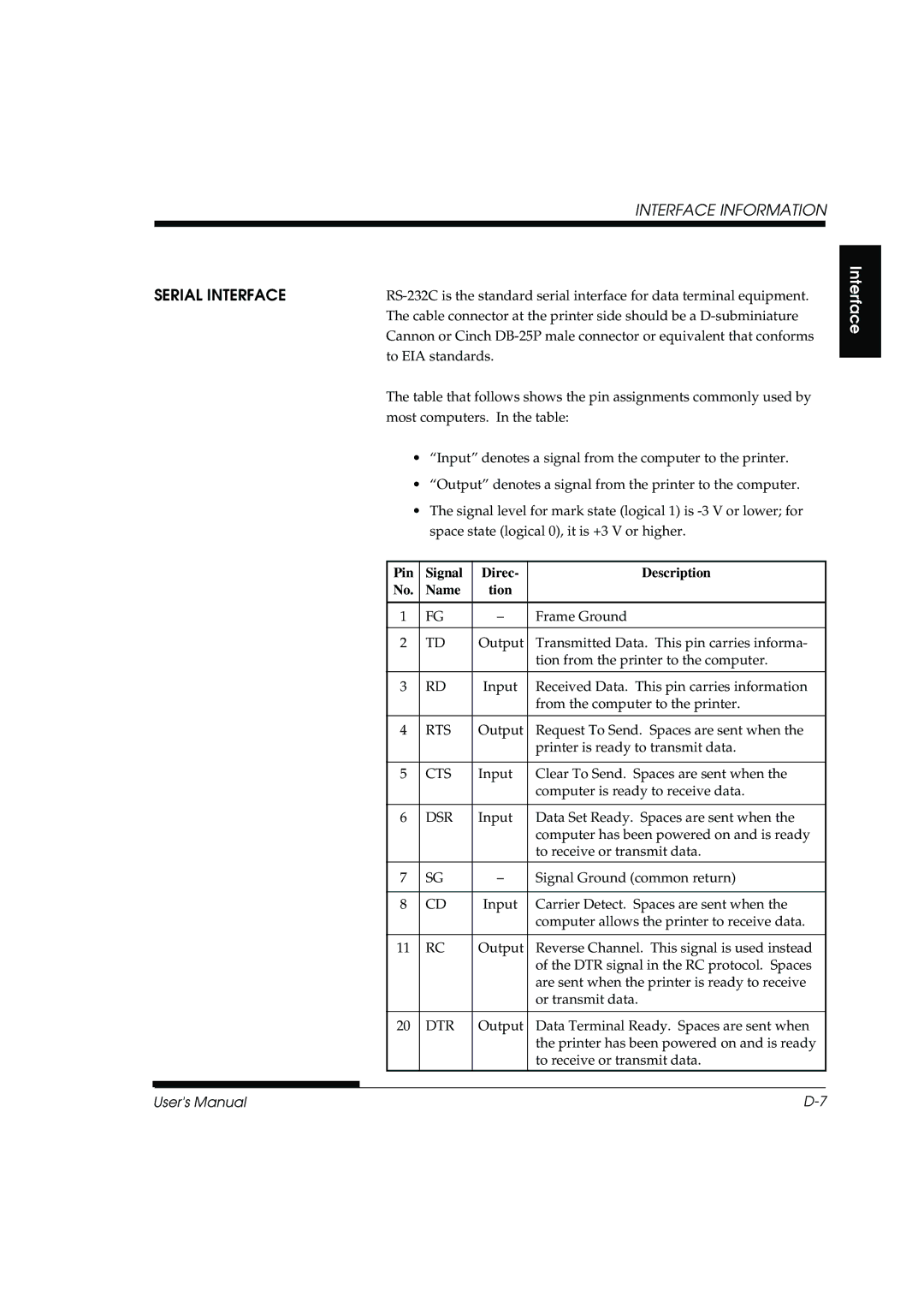
Interface Information
Inprm
Pin Return
Direc Description Pin No
Slct
Pin Return Signal Direc Description Pin No Name
Name Tion
Busy
CTS
Pin Signal Direc Description Name
Serial Interface
RTS
Serial Options
DSR
XON/XOFF
Protocol Description
Code Page 437 Character Set
Character Sets 1 DPL24C Plus and Ibmê XL24E Emulation
Italic Character Set
Character Sets
Italic and Graphics
Character Sets ESC/P2
Character
National Character Sets ALL Emulations
PAGE852/PG852-T Code PAGE855 Code
PAGE865 Code Page 865Nordic PAGE866 Code Page 866Cyrillic
PAGE860 Code Page 860Portugal
POLISH/POLSH-T Polish MAZOWIA/MAZOW-T Mazowian
HUNGARY/HUNG-T Hungarian SLOV/SLOV-T Slovenian
Character Sets
ELOT928 Elot PG-DHN Code Page DHN
IBM437 IBM IBM851 IBM
Character Sets
MIK
Macedon Macedonian
ABG
Decgr
PG-MAC
HBR DEC
PAGE862
National Character Sets DPL24C Plus and IBM XL24E Emulation
Danish1 SPANSH1 Spanish1
DANISH1/NORWEGN Danish1/Norwegian DANISH2 Danish2
ESC/P2 Emulation
DANISH1
Character Sets
DANISH2 Danish2 Korea Korea
Norwegn Norwegian French French
Resident Fonts ALL
Legal Legal
National Character
Sets and Supported
PAGE855
National Name Character set Setup menu
ECMA94
PAGE852
PG-MAC
Resident font National Name Character set Setup menu
MIK
ABG ABY
OCR-B OCR-A
Resident Fonts
Resident Fonts
Courier Scalable Normal Bold Italic
Bold Italic Timeless Scalable Normal
A4 size Application software
Ascii
Baud rate Bidirectional printing Bit Bottom feed Buffer
Glossary of Terms
Commonly used fonts
Offline Online
Interface
GL-5
Serial interface
Setup mode
Self-test
Separator
Top-of-form TOF Tractor feed Unidirectional printing
Top margin
GL-8
Index
CR-CODE
Index
SELF-TST Almnt
Menu
Power
Ribbon subcassette A-1 RS-232C serial interface
Others
IN-8
Fujitsu Canada INC
C147-E042-05EN