Manuals
/
Fujitsu
/
Computer Equipment
/
Server
Fujitsu
manual
Mechanical requirements TX200 S6
Models:
TX200 S6
1
51
126
126
Download
126 pages
61.66 Kb
48
49
50
51
52
53
54
55
Troubleshooting
Specification
Install
Error codes
Timer-controlled switch-on/off
Labels LAN activity indicator
Connecting cables
Dimension
Configuring the server
Accessible drives
Page 51
Image 51
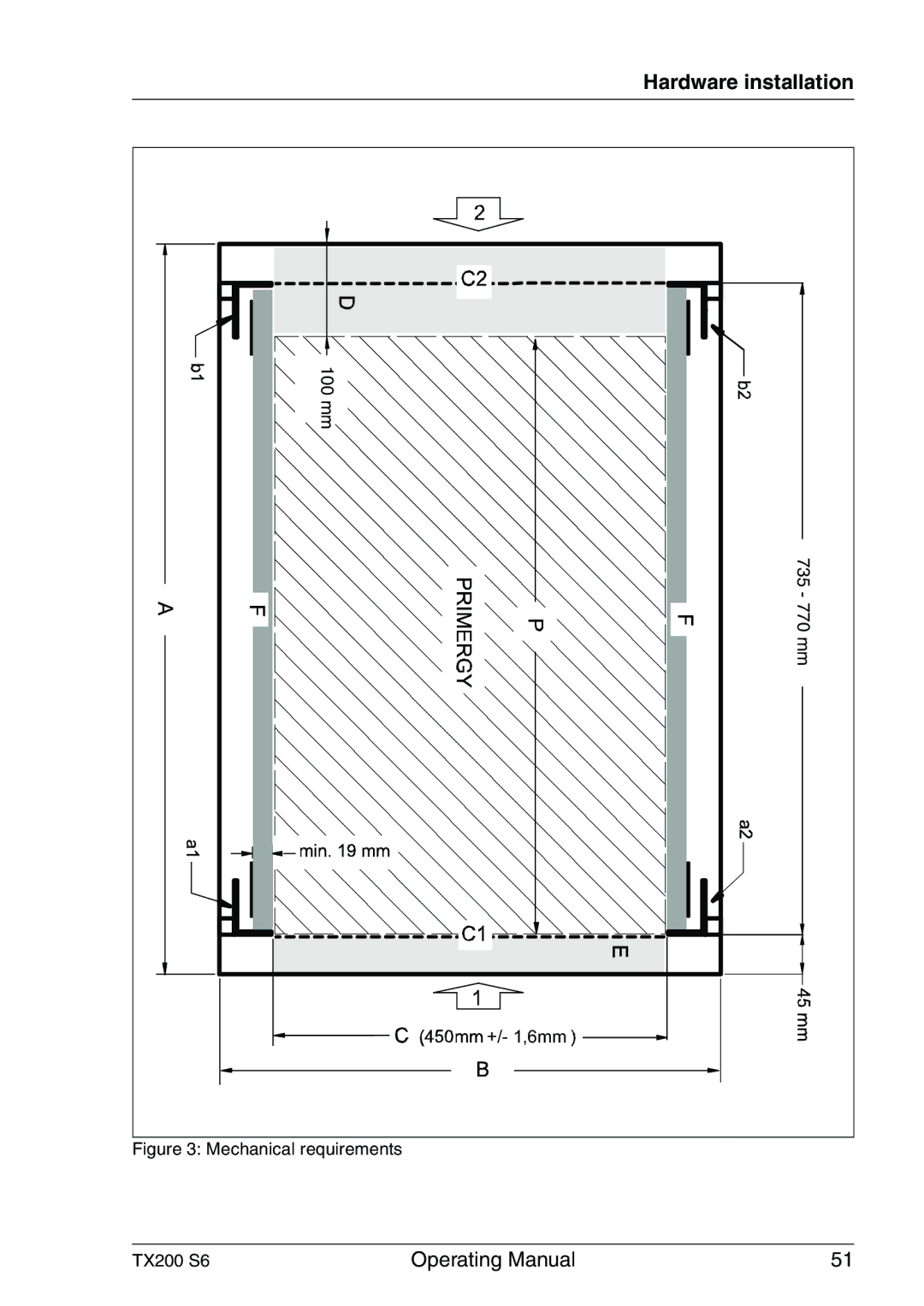
Hardware installation
100 mm
735 - 770 mm
+/- 1,6mm
Figure 3: Mechanical requirements
TX200 S6
Operating Manual
51
Page 50
Page 52
Page 51
Image 51
Page 50
Page 52
Contents
Primergy TX200 S6 Server
Comments… Suggestions… Corrections…
Copyright and Trademarks
Certified documentation according to DIN EN ISO
Aluminum electrolytic capacitors
For your safety
High safety use
Radio interference
Measures against momentary voltage drop
Harmonic Current Standards
Only for the Japanese market About Sata hard disk drives
Only for the Japanese market
Operating Manual
Contents
Control elements and indicators
Contents
Screen remains blank
Appendix server specification 115 Index 121
Preface
Concept and target groups for this manual
Documentation overview
Preface
Preface Further sources of information
Customer Self Service CSS
Features
Preface System board
Trusted Platform Module TPM
Slots for expansion cards
For up to eight 2.5-inch SAS/SATA hard disk drives
Preface Hard disk drives
SAS/SATA RAID controller
Preface Onboard Sata controller
Accessible drives
Cooling
Preface Power supply
Preface High level of availability and data security
Preface IRMC S2 with integrated management LAN connector
Preface Server management
Service and support
Preface ServerView Installation Manager
Preface ServerView Remote Management
Notational conventions
Technical data
Electrical data
Compliance with regulations and standards
Ventilation clearance
Preface Mechanical specifications Floorstand Rack
Weight
Maintenance area for the floorstand model
TX200 S6
Installation steps, overview
Installation steps, overview
Important information
Safety instructions
Important information Before starting up
Installation and operation
Important information
Important information
Batteries
TX200 S6
Never remove parts of the optical drive casing
Laser information
ESD label
Important information Other important information
Energy Star
FCC Class a Compliance Statement
CE conformity
Transporting the server
For the Japanese market, please refer to 安全上の注意およびその 他の重要情報
Packaging information
Environmental protection
Environmentally-friendly product design and development
Energy-saving information
Returns, recycling and disposal
Labels on plastic casing parts
Hardware installation
Minimum acclimatization time
Hours
Unpacking the server
Hardware installation
Vcaution
Setting up the floorstand model
Mounting the anti-tilt bracket
Mounting the anti-tilt bracket
Installing/removing the rack model
Rack system requirements
Fujitsu rack systems
3rd party racks
For 19-inch standard rack for the Japanese market
Mechanical requirements TX200 S6
Hardware installation
Fitting the support bracket
Hardware installation Fitting the support bracket
Hardware installation Installing the support systems
Insert the server see Inserting the server on
Inserting the server a
Hardware installation Inserting the server
Installation in 3rd party racks
Racks with installation depth smaller/greater than 735 mm
Racks with installation depth of 735 mm
Connector panel on the rear side
Connecting devices to the server
Hardware installation Connecting the monitor
Connecting the server to the mains
Connecting the server to the mains
Using cable ties
Using cable ties
Disconnecting cables
Connecting cables
Hardware installation
Access to the drives floorstand model
Access to the accessible drives
Starting up and operation
Removing the drive cover from the hard disk drive cover
Starting up and operation
Removing the hard disk cover
Access to the HDD modules
Front of server
Control elements and indicators
Control elements
Starting up and operation ID card
Starting up and operation LEDs on the control panel
Indicators on the drives DVD drive activity indicator
Indicators on the 3.5 inch and 2.5 inch HDD modules
Starting up and operation Hard disk drive indicators
Rear of server
Starting up and operation
LAN activity indicator shared LAN
Starting up and operation LAN indicators
LAN activity indicator management LAN
LAN transfer rate indicator management LAN
Indicators on the hot-plug power supply units
Switching the server off
Switching the server on and off
Switching the server on
System already installed
Power button override
Timer-controlled switch-on/off
Ring indicator
After power failure
Configuring the server
Configuring the onboard Sata controller
Configuring the SAS/SATA RAID controller
LSI RAID / Scsi Controllers
Advantages of the ServerView Installation Manager
Installing the operating system
Configure onboard Sata controller
Cleaning the server
Property and data protection
Bios Setup security functions
Property and data protection
Power supply overloaded
Troubleshooting and tips
Power-on indicator remains unlit
Power cable incorrectly connected
Screen remains blank
Server switches itself off
Flickering stripes on monitor screen
No screen display or display drifts
Monitor does not support the set horizontal frequency
Drives reported as dead when starting system
RAID controller configuration incorrect
Incorrect date and time
Error message on screen
RAID controller is not configured for this drive
Added drive reported as defective
Page
CSS components
CSS components
Hot-plug power supply units optional
Replacing the hot-plug power supply unit
Hot-plug components
Hot-plug hard disk drives
CSS components
CSS components 2.1 3.5-inch HDD module and dummy module
For description see section Hard disk drive indicators on
CSS components 2.2 2.5-inch HDD module and dummy module
CSS components Handling hard disk drives and HDD modules
CSS components Floorstand removing the hard disk cover
CSS components Removing/installing the dummy module
Unlocking the 3.5-inch and 2.5-inch HDD modules
Installing the 3.5-inch and 2.5-inch HDD modules
CSS components Installing the HDD module
CSS components Removing the HDD module
Open the server see section Opening the server on
Non-hot-plug components
Opening the server example floorstand model
Opening the server
System fan 2 and system fan 2&4
CSS components Removing system fan 2
System fan 1 and system fan 1&3
Removing system fan 1
Example Removing system fan 1&3
Identifying a CSS component
Installing a new memory module
Replacing a memory module
Removing a defective memory module
Replacing the system fan
Replacing system fan 2
Replacing system fan 1
Removing a defective expansion card
Replacing an expansion card
Installing a new expansion card
CSS components Installing a new expansion card
Installing system fan 1
Reinstalling the fans and closing the server
Installing system fan 2
CSS components Installing system fan 2
Closing the server example floorstand model
CSS components Closing the server
Interfaces
Appendix server specification
Memory Modules Configuration
Processor
Onboard or integrated controllers
Appendix server specification
PCI-Slots
Drive bays
Operating Panel
Environmental
Dimensions Base unit specific
Electrical values
120 Operating Manual
Index
Bios
Index
Labels LAN activity indicator
Sddc
Unpacking, server USB connector
Top
Page
Image
Contents