6HFXULW\
Installation Instructions
Concord Ultra
466-2061Rev C
FCC Part 15 Class B
Notices
FCC Part 15 Information to the User
ACTA Part
Installing the System
Contents
Planning the Installation
About This Manual
Testing the System
Programming the Panel
Troubleshooting
Special Installation Requirements
UL Listed Installations
Required Setting
Testing
Default
SIA System Requirements
Central Station Reporting
Planning the Installation
UL Canada Listed Installations
Function
SuperBus 2000 Touchpads
Supervised Wireless Siren
Standard Panel
SnapCards
SuperBus 2000 8Z Input Module HIM
SuperBus 2000 Cellular Backup Module
SuperBus 2000 Wireless Gateway Module
SuperBus 2000 4-RelayOutput Module HOM
Wire Length
Total System Power and Wire Length Guidelines
Power
Determine the Panel Location
Wire Type
Table 2: Total System Wire Length Allowed
Max. Wire Length
Total System Wire
Table 3: Minimum Device Current Draw
Table 4: Wire Requirements
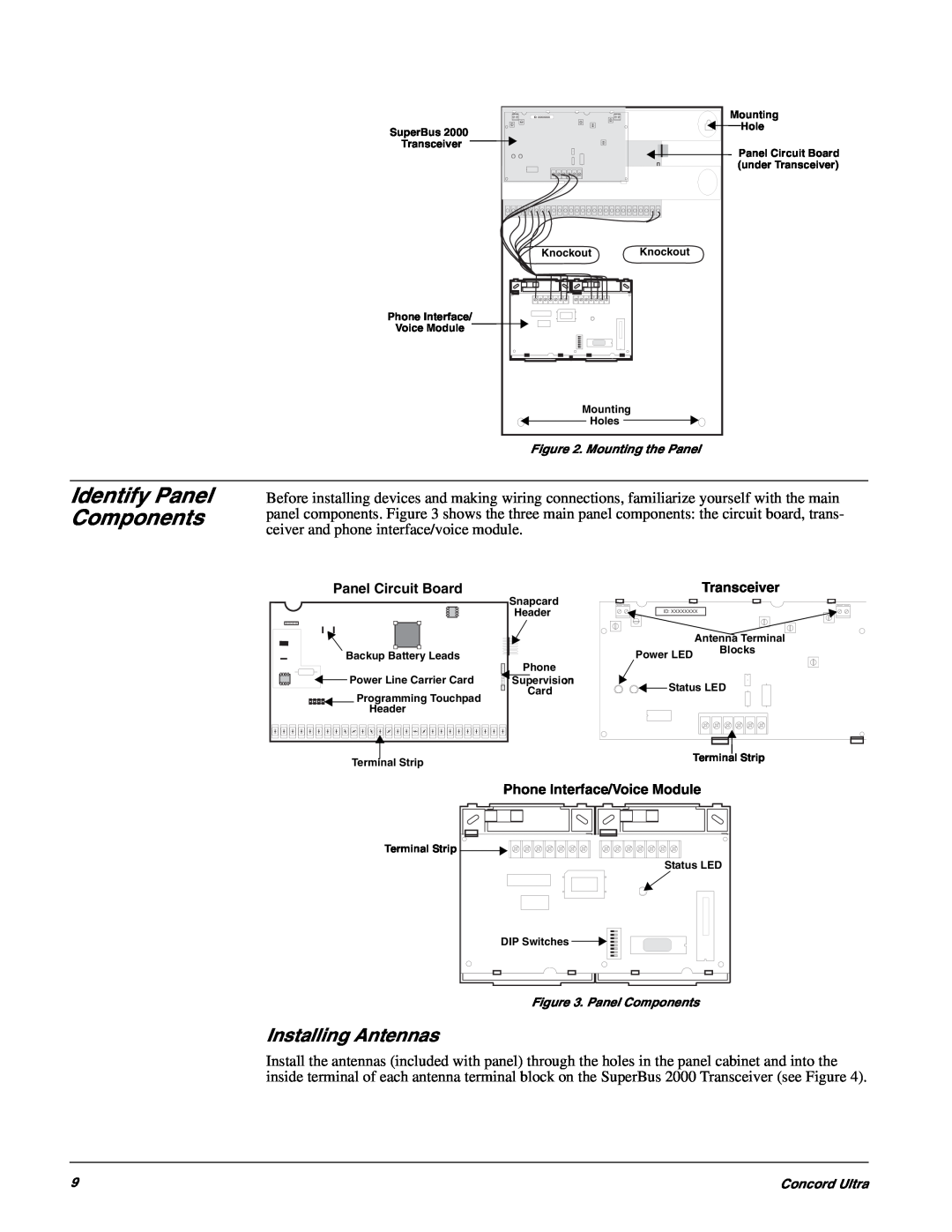
Mounting the Panel
Installing Antennas
Identify Panel Components
Figure 4. Installing the Antennas
Connecting the Panel to Earth Ground
Installing Optional SnapCards
Figure 5. Connecting the Panel to Earth Ground
Connecting 2-WireSmoke Detectors
Connecting Detection Devices to Panel Zone Inputs
Connecting Intrusion Detection Devices
Table 5 Panel Minimum Available Power
Connecting Speakers
Connecting 4-WireSmoke Detectors
15-WattSpeaker
Connecting Piezo Sirens
Hardwire Interior Speaker
Interior Sirens
Installing Supervised Wireless Sirens
Exterior Sirens
1.Power up the panel see “Powering Up the Panel”
Installing SuperBus 2000 Modules
SuperBus 2000 Phone Interface/Voice Module
Wiring-Speaker
SuperBus 2000 Energy Saver Module
SuperBus 2000 8Z Input Module
SuperBus 2000 Cellular Backup Module
SuperBus 2000 Automation Module
SuperBus 2000 4-RelayOutput Module
Installing an RJ-31XPhone Jack
SuperBus 2000 Wireless Gateway Module
Setting Device Address on SuperBus 2000 Devices
Figure 21. Connecting the SuperBus to the Panel
Connecting the AC Power Transformer
the Panel
Powering Up the Panel
Programming
Entering Program Mode
Table 6: Touchpad Button Functions
Touchpad Button Programming Functions
Moving Through Program Mode Tiers and Menus
Figure 26. Tier 1 Program Menus
Programming Tier 1 Menu Items
Security-GlobalDefault =
Using Shortcut Numbers
Installer Code
Security-GlobalDefault =
Security-GlobalDefault = none
Access Code Lock
SIA False Alarm Reduction
Security-GlobalDefault = on
Security-Partition 1-2Default = on
Security-Partition 1-2Default = on
Security-Partition 1-2Default = on
Quick Exit partition 1: 0012, partition 2:
Security-Partition 1-2Default = none
Keyswitch Sensor partition 1: 0015, partition 2:
Keyswitch Style partition 1: 0016, partition 2:
Security-Partition 1-2Default = transition
Phones-CSPhone 1-3Defaults: CS
Phones-CSPhone 1-3Defaults: CS
RPTS OFF/ON current setting, press
RPTS OFF/ON current setting, press
phone 3:
phone 3:
Phones-PagerPhone 1-5Default = on
Phones-CSPhone 1-3Defaults: CS
Phones-PagerPhone 1-5Default = none
Phones-PagerPhone 1-5Default = off
Latchkey Rpts pager 1: 0135, pager 2: 0145, pager
0153, pager 4: 0163, pager 5:
0154, pager 4: 0164, pager 5:
0155, pager 4: 0165, pager 5:
Phone Options-GlobalDefault = on
Auto Test Reset
Phones-DownloaderPhone Default = none
Phone Options-GlobalDefault = off
Phone Options-GlobalDefault = on
Cancel Message
Phone Options-GlobalDefault = on
Phone Options-GlobalDefault = on
Phone Options-GlobalDefault = 15 sec
Call Wait Cancel
Remote Access partition 1: 0211, par
Phone Options-GlobalDefault = none
Phone Options-Partition 1-2Default = on
Phone Options-Partition 1-2Default = on
Phone Options-Partition1 only Default = none
Phone Options-Partition 1-2Default = off
RF Tx Timeout
Phone Access Key partition 1: 0216, partition 2:
Timers Menu
Phone Options-Partition 1-2Default = #
Timers-GlobalDefault 4 sec
Activity Timeout
Timers-GlobalDefault = 7 days
Timers-GlobalDefault = 24 hours
Timers-Partition 1-2Default = 4 min
Siren Timeout partition 1: 0313, partition
Timers-Partition 1-2Default = 4 min
Timers-Partition 1-2Default = 22:00 10:00 pm
Touchpad Options-Partition 1-2Default = on
display shows HOUSE CODE nn-x current setting
Touchpad Options-GlobalDefault = none
Touchpad Options-Partition 1-2Default = on
Touchpad Options-Partition 1-2Default = off
Back In Service
Touchpad Options-Partition 1-2Default = off
Reporting-GlobalDefault = off
Two Trip Error
Low CPU Battery
Battery Restoral
Reporting-GlobalDefault = on
Reporting-GlobalDefault = off
Reporting-GlobalDefault = off
Reporting-GlobalDefault = off
Reporting-GlobalDefault = weekly
Reporting-Partition 1-2Default = off
Reporting-GlobalDefault =
Reporting-GlobalDefault = off
Reporting-Partition 1-2Default = off
Reporting-Partition 1-2Default = off
Reporting-Partition 1-2Default = off
Reporting-Partition 1-2Default = off
Reporting-Partition 1-2Default = off
Disable Trouble Beeps
Freeze Alarm partition 1: 06107, partition 2:
Alarm Verify partition 1: 06108, partition 2:
Reporting-Partition 1-2Default = off
Siren Options-GlobalDefault = off
Siren Options-GlobalDefault = off
Siren Options-GlobalDefault =
Siren Options-Partition1 Default = off
Learn Sensors
Table 7: How to Trip Sensors
Sensors Default = none
Sensors Default = none
Sensors Default = none
Sensors Default = none
Sensor Text
Audio Verification-Partition1 Default =
Access Timeout
Audio Verification-Partition1 Default = off
Audio Verification-Partition1 Default = off
Audio Verification-Partition1 Default = 02 sec
Access Code
Accessory Modules Menu
This setting determines how long AVM access
Output Programming
Device ID
Partition Assign
Status Beeps
Temperature
Key Beeps
Freeze Temp
Cellular System
output 3 10112, output
Acc. Modules--SnapCards-OutputText Default = none
Output Text output 1: 10110, output 2:
Onboard Options Menu
rent setting
Two Wire Smoke
Onboard Options-InputsDefault = off
Onboard Options-InputsDefault = off
Entering User Programming Mode
Onboard Options-Output Text-Output1, 2 Default
Exiting Programming Mode
Output Text Output 1-1120,Output
User Codes-Reg.User Codes-UserNNN Default = none
Time and Date Default = 00:00
Time and Date Default = 01/01/00
Time
Partition Jump 030nnn3 where nnn=user number
Direct Bypassing 030nnn1 where nnn=user number
Remote Access 030nnn2 where nnn=user number
System Tests 030nnn4 where nnn=user number
User Codes-SystemMaster Code Default =
Latchkey Report 030nnn5 where nnn=user number
User Codes-PartitionMaster Code Default = none
Options Default = on
Options Default =
Volume
Set Up Schedules Menu
Options Default =
Attach Schedules To Events Default = off
Set Up Schedules 05XXY, where
Default = 00:00
XX=schedule 00 thru 15 and
3.Press A or B until the desired light appears
Energy Saver Default = 90F
Attach Schedules To Events Default = off
Energy Saver Default = 50F
Attach Lights To Sensors Default =
Table 9: Basic Touchpad Commands
Basic System Commands
Default = N/A
Downloader Programming
Table 9 Basic Touchpad Commands Continued
Testing Zones/Sensors
If a Wireless Sensor Does Not Test
Table 10: Pager System Event Codes
Testing Phone Communication
Testing Central Station/Pager Communication
Table 11: Pager Sensor/Zone Code and Numbers
Testing the Energy Saver Module ESM
Testing Outputs and Sirens
Testing Light Control
Table 12: System Alarm Sounds
Adjusting Touchpad Display Contrast
Testing Cellular Backup Communication
Table 13: Current Phone Settings
2.Check for proper panel and transformer wiring
System indicates Sensor/Touchpad nn low battery
Central station/pager is not receiving reports
System doesn’t go into alarm when zone is tripped
Smoke sensor beeps once every 44 seconds
Cellular backup report does not occur
Module doesn’t communicate with alarm.com
Table A1: Wireless Devices
Appendix A System Planning Worksheets
Table A2: Hardwire Devices
Table A3: Zone and Sensor Assignments
Table A3: Zone and Sensor Assignments Continued
Table A3 Zone and Sensor Assignments Continued
Concord Ultra
Setting
Table A4 System Settings Index and Record
Setting reference default
Shortcut No
Exception Reports phones Off
Phone Test On
Appendix B Reference Tables
Table B1: Sensor Group Characteristics Continued
Cross-Zoning
Table B2: Item Numbers and Sensor Text
System Event
Table B3: System Event Trigger Numbers
Table B4: Sensor Group Event Trigger Numbers
Description
Sensor Group
Table B4 Sensor Group Event Trigger Numbers
Table B5: Sensor Number Event Trigger Numbers
Trigger No
Table B5: Sensor Number Event Trigger Numbers
Sensor
Table B6: System Feature Event Trigger Numbers
Table B5: Sensor Number Event Trigger Numbers
Feature
Table B6: System Feature Event Trigger Numbers
Table B7: Response Characteristics
Response Characteristics
Notes for Table B8: Response Numbers
Concord Ultra
Concord Ultra
#* # * #
To Enter Programming Mode: 8 + Installer or
Dealer Code + 0 +
Tier 2 Menus Continued
#* # * # * # * # * #
Concord Ultra
#* # * #
#* #
Timers
Concord Ultra
Concord Ultra
#* #
Concord Ultra
Downloader Code
SIA False Alarm
Software Version
Central Station Reports
Disarming
Exit Delay
Dialer Abort Delay
Downloader
Concord Ultra
Optional SuperBus 2000 Module Connections