Operation / Data Log
Example Event Log 2: Pump cycle of an injector valve system with a pressure switch feedback.
Date | Time | Description |
9/29/2010 | 13:28:12 | Venting Completed |
9/29/2010 | 13:23:12 | Venting Detected |
9/29/2010 | 13:23:11 | Pump Run Off |
9/29/2010 | 13:23:11 | P1 Pressure Completed |
9/29/2010 | 13:22:20 | Pump Run On |
Venting Detected | In an injector system, the pump on cycle |
| has completed and the system is cur- |
| rently venting pressure through the vent |
| valve. |
|
|
Prelube Initiated | The pump has entered a prelube delay |
| after powering up. |
|
|
Prelube Completed | The pump has completed prelube delay |
| and will begin a pump on cycle. |
|
|
Successful Pin | The pin code was successfully entered |
Code Entry | and the user has entered setup mode. |
|
|
Common System Events are listed below.
Pump Run On | The pump entered an on cycle and is | |
| operating and dispensing material. | |
|
| |
Pump Run Off | The pump entered an off cycle and is | |
| not dispensing. | |
|
| |
Pump Run Can- | A pump on cycle was cancelled by | |
celled | pressing the cancel button on the front | |
| panel and holding it for 3 seconds. | |
|
| |
G3 Power On | The pump powered on. | |
|
| |
G3 Power Off | The pump powered off. | |
|
| |
Program Variable | The setup mode was entered. | |
Change |
| |
|
| |
C1 Cycle Detected | The system is set up to monitor a prox- | |
| imity switch on a divider valve using the | |
C2 Cycle Detected | ||
sensor input (C1, C2, and/or C3) and | ||
| ||
C3 Cycle Detected | ||
has detected one divider valve cycle. | ||
| ||
|
| |
C1 Cycle Com- | The system is set up to monitor a prox- | |
pleted | imity switch on a divider valve using the | |
| sensor input (C1, C2, and/or C3) and | |
C2 Cycle Com- | ||
has achieved the number of counts | ||
pleted | ||
required by the system for that input, | ||
| ||
C3 Cycle Com- | ||
completing a pump on cycle. | ||
pleted | ||
| ||
|
| |
P1 Pressure Com- | The system is set up to monitor a pres- | |
pleted | sure switch for an injector system using | |
| sensor input (P1, P2, and/or P3), the | |
P2 Pressure Com- | ||
system has achieved pressure and the | ||
pleted | ||
switch has activated, completing a | ||
| ||
P3 Pressure Com- | ||
pump on cycle. | ||
pleted | ||
| ||
|
| |
Machine Count | The system is set up to monitor a sen- | |
Completed | sor on the equipment being lubricated | |
| using the machine count input and has | |
| achieved the number of counts required | |
| by the system for that input, completing | |
| a pump off cycle and initiating a pump | |
| on cycle. | |
|
| |
Local Manual Run | The manual run button was pressed, | |
Initiated | initiating a pump on cycle. | |
|
| |
Remote Manual | The remote manual run button was | |
Run Initiated | pressed initiating a pump on cycle. | |
|
|
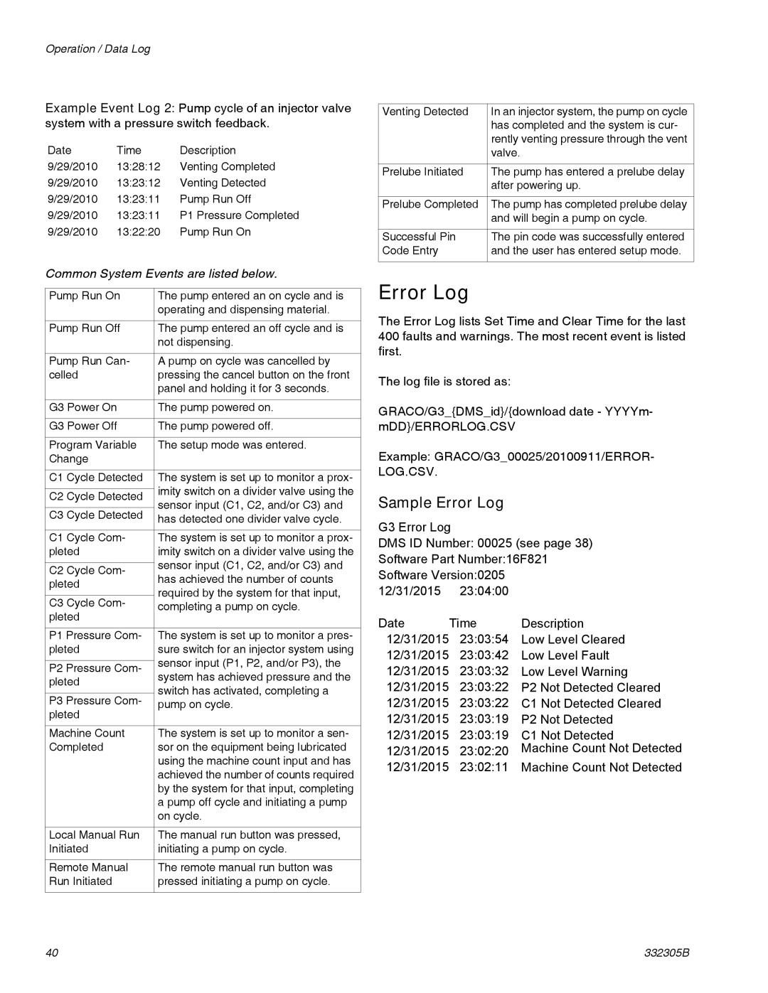
Error Log
The Error Log lists Set Time and Clear Time for the last 400 faults and warnings. The most recent event is listed first.
The log file is stored as:
GRACO/G3_{DMS_id}/{download date - YYYYm- mDD}/ERRORLOG.CSV
Example: GRACO/G3_00025/20100911/ERROR- LOG.CSV.
Sample Error Log
G3 Error Log
DMS ID Number: 00025 (see page 38) Software Part Number:16F821 Software Version:0205
12/31/2015 23:04:00
Date | Time | Description |
12/31/2015 | 23:03:54 | Low Level Cleared |
12/31/2015 | 23:03:42 | Low Level Fault |
12/31/2015 | 23:03:32 | Low Level Warning |
12/31/2015 | 23:03:22 | P2 Not Detected Cleared |
12/31/2015 | 23:03:22 | C1 Not Detected Cleared |
12/31/2015 | 23:03:19 | P2 Not Detected |
12/31/2015 | 23:03:19 | C1 Not Detected |
12/31/2015 | 23:02:20 | Machine Count Not Detected |
12/31/2015 | 23:02:11 | Machine Count Not Detected |
40 | 332305B |
