Maintenance
Maintenance
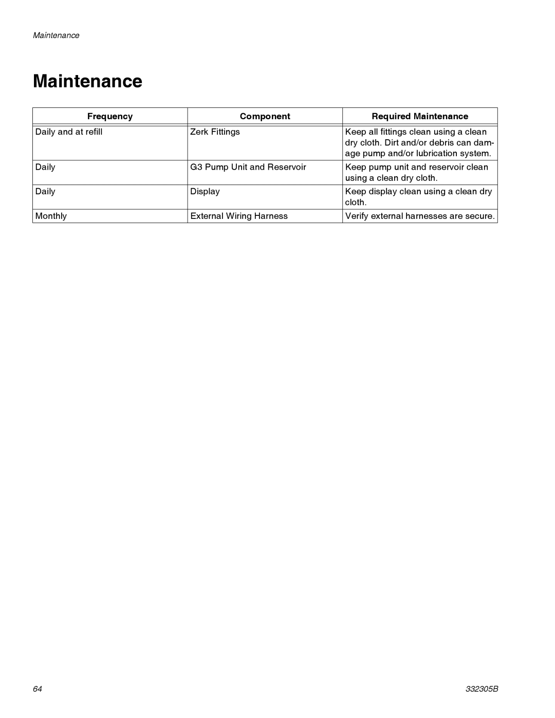
Frequency | Component | Required Maintenance |
|
|
|
|
|
|
Daily and at refill | Zerk Fittings | Keep all fittings clean using a clean |
|
| dry cloth. Dirt and/or debris can dam- |
|
| age pump and/or lubrication system. |
Daily | G3 Pump Unit and Reservoir | Keep pump unit and reservoir clean |
|
| using a clean dry cloth. |
Daily | Display | Keep display clean using a clean dry |
|
| cloth. |
Monthly | External Wiring Harness | Verify external harnesses are secure. |
64 | 332305B |