Max Model Setup
Max Model Setup
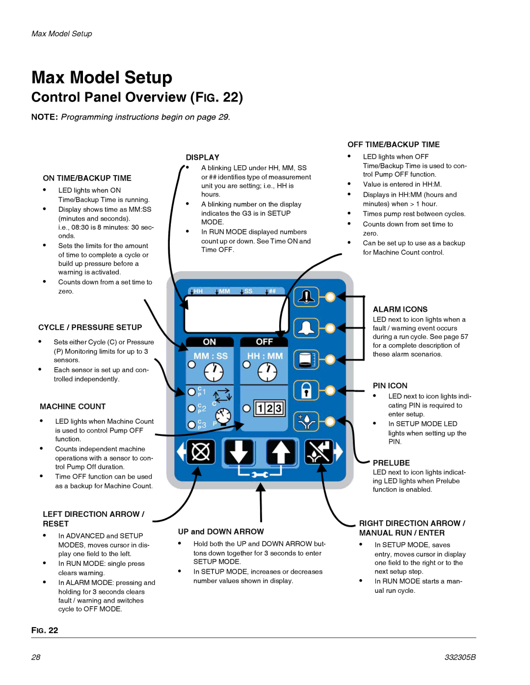
Control Panel Overview (FIG. 22)
NOTE: Programming instructions begin on page 29.
OFF TIME/BACKUP TIME
ON TIME/BACKUP TIME
•LED lights when ON Time/Backup Time is running.
•Display shows time as MM:SS (minutes and seconds).
i.e., 08:30 is 8 minutes: 30 sec- onds.
•Sets the limits for the amount of time to complete a cycle or build up pressure before a warning is activated.
•Counts down from a set time to zero.
CYCLE / PRESSURE SETUP
•Sets either Cycle (C) or Pressure
(P) Monitoring limits for up to 3 sensors.
•Each sensor is set up and con- trolled independently.
MACHINE COUNT
•LED lights when Machine Count is used to control Pump OFF function.
•Counts independent machine operations with a sensor to con- trol Pump Off duration.
•Time OFF function can be used as a backup for Machine Count.
LEFT DIRECTION ARROW / RESET
•In ADVANCED and SETUP MODES, moves cursor in dis- play one field to the left.
•In RUN MODE: single press clears warning.
•In ALARM MODE: pressing and holding for 3 seconds clears fault / warning and switches cycle to OFF MODE.
DISPLAY
![]() • A blinking LED under HH, MM, SS or ## identifies type of measurement unit you are setting; i.e., HH is hours.
• A blinking LED under HH, MM, SS or ## identifies type of measurement unit you are setting; i.e., HH is hours.
•A blinking number on the display indicates the G3 is in SETUP MODE.
•In RUN MODE displayed numbers count up or down. See Time ON and Time OFF.
UP and DOWN ARROW
•Hold both the UP and DOWN ARROW but- tons down together for 3 seconds to enter
SETUP MODE.
•In SETUP MODE, increases or decreases number values shown in display.
•LED lights when OFF Time/Backup Time is used to con- trol Pump OFF function.
•Value is entered in HH:M.
•Displays in HH:MM (hours and minutes) when > 1 hour.
•Times pump rest between cycles.
•Counts down from set time to zero.
•Can be set up to use as a backup
for Machine Count control.
ALARM ICONS
LED next to icon lights when a fault / warning event occurs during a run cycle. See page 57 for a complete description of these alarm scenarios.
PIN ICON
• LED next to icon lights indi- cating PIN is required to enter setup.
• In SETUP MODE LED lights when setting up the PIN.
![]()
![]() PRELUBE
PRELUBE
LED next to icon lights indicat- ing LED lights when Prelube function is enabled.

 RIGHT DIRECTION ARROW / MANUAL RUN / ENTER
•In SETUP MODE, saves entry, moves cursor in display one field to the right or to the next setup step.
•In RUN MODE starts a man- ual run cycle.
FIG. 22
28 | 332305B |