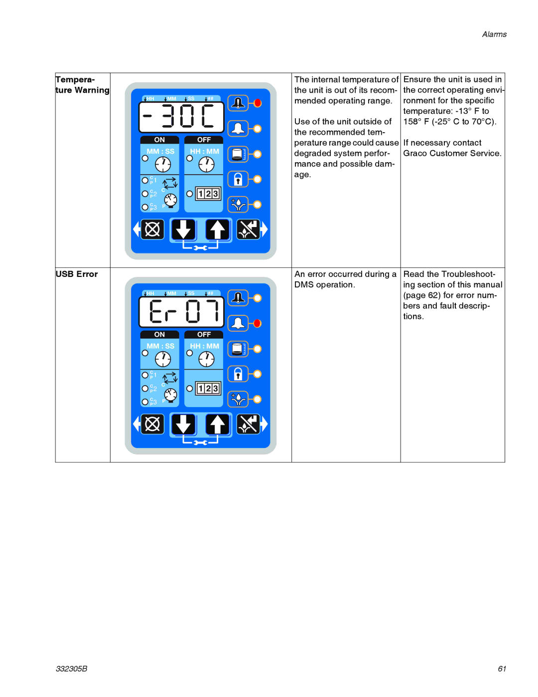
Part Nos., page
Important Safety Instructions
G3 Max Automatic Lubrication Pump
Instructions
332305B
Contents
2 Liter Models
Part / Model Numbers
4 Liter Models
Part
12 Liter Models
8 Liter Models
16 Liter Models
Part
h g i j
Understanding the Model Number
k m n p
ELECTRIC SHOCK HAZARD
Warnings
EQUIPMENT MISUSE HAZARD
SKIN INJECTION HAZARD
PLASTIC PARTS CLEANING SOLVENT HAZARD
PRESSURIZED EQUIPMENT HAZARD
MOVING PARTS HAZARD
Grounding
Installation
Component Identification
Divider Installations
Typical Installation
Injector Installations
Installation
AUTOMATIC SYSTEM ACTIVATION HAZARD
Choosing an Installation Location
Fuses
System Configuration and Wiring
NOTICE
Alarm Relay Response
Alarm Output and Remote Illumination Response
1 second
Wiring and Installation Diagrams
Connector on Housing
Power DIN AC - 15 foot: Part No. 16U790
Connector on Cable
Example Wiring Diagram
Pin and Related Wire Color FIG.
Power DIN DC - 15 foot Part No. 16U790
Connector on Housing
Connector on Cable
Connector on Housing
Power CPC DC -15foot Part No
Connector on Cable
Example Wiring Diagram
Pin and Related Wire Color FIG.
Power CPC DC - 5 Wire
Part No.: 126218: 15 ft 4.5 m
Part No.: 126219: 20 ft 6.1 m
Sink NPN 2 or 3 wire
Example Wiring Diagram
Source PNP 2 or 3 wire
Inputs M12
Pin-out
Connector on Housing
Vent Valve Outputs
Example Wiring Diagram
Connector on Housing
Alarm Outputs
Example Wiring Diagram
Pin-out
Part No. 124300: Field Wireable Pin Out M12
Part No. 124333: Cable Pin Out M12 Wire Colors
Wire Colors
Part No. 124594: 4 Pin Eurofast Field
Wireable Connector
Part No. 124595: 5 Pin Eurofast Field
Wireable Connector
Connecting to Auxiliary Fittings
Setup
Pressure Relief
Pressure Relief Valves
Loading Grease
Setting Pump Outlet Volume
Output Volume / Minute
No. Spacers
Models without a follower plate
Changing Greases
Models with a follower plate
Priming
Filling Oil Unit
Quick Setup Guide
Quick Setup Guide
332305B
Control Panel Overview FIG.
Max Model Setup
Max Model Setup
Entering Setup Mode
Powering Units With Controllers
Entering a PIN Code to Access Setup Mode
Programming the Max Model
Enter the Year
Setting the Real Time Clock
Enter the Month
Enter the 2-digitDate
Programming ON Duration
Cycle C1, C2, C3 Setup
Backup Time
Pressure Control P1, P2, P3 Setup
Input Not Used
Examples
Programming Backup Time
ON Time
Programming ON Time
Machine Count
PUMP OFF / REST Setup
Backup Time
Programming Backup Time
OFF Time
Programming OFF Time
Prelube
Prelube Delay
Setting Prelube
Uploading Pump Program Settings to the Pump
Storing Pump Program Settings to the Flash Drive
DMS Models Only
Downloading Data
Viewing the UNIT DMS ID Number
System Event Log
Operation / Data Log
Sample System Event Log
Sample Error Log
Error Log
Common Error Log entries are listed below
Sample Functional Summary
Functional Summary
Number of Cycles
Operation / Data Log
332305B
Sample Technical Summary
Technical Summary
Setting
Advanced Programming
Why Use This?
Advanced
Selecting Advanced Setup Options
Entering Advanced Setup
Entering a PIN Code for the First Time
A1 - Setting Up PIN Code
A3 - Vent Valve Time
A2 - Low Level Alarm Time
Pump ON mode only
FIG. To set the Alarm Retry
A-4Alarm Retry
To set Vent Valve Time
A-5Active Alarm
ON OFF MM : SS HH : MM
A-7-Constant Alarm Output on Fault
Time Control
Run Mode
ON OFF MM : SS HH : MM
Cycle Control
Lubrication Mode Pump ON Controls
ON OFF MM : SS HH : MM
Pressure Control
ON OFF MM : SS HH : MM
Backup Time
FIG.
ON OFF MM : SS HH : MM
Machine Count
Backup Time
ON OFF MM : SS HH : MM
FIG. OFF Time
Prelube / Prelube Delay
Additional Controls
Prelube Delay
Venting
332305B
Manual Run Cycle
Fault / Warning Scenarios
Alarms
Cycle Pressure
Low Level Fault
Machine Count Fault
Cycle Pressure Fault
Graco Customer Service
Fault
System
Motor Cur
Tempera
USB Error
ture Warning
Problem
Troubleshooting
Solution
Cause
In an Injector System without sensor
Required Maintenance
Maintenance
Frequency
Component
Follower Plate Models Only 4340a 44 42 41
Parts - 2 Liter Models
40b Low Level Grease Models Only 35 57 271
15 13
Parts - 4 Liter and Larger Models
Part
Parts
Description
Part
BOARD, circuit, Max, models
RESERVOIR, 8 liter, grease
WASHER, low level, models
Pressure Relief Valves
Installation and Repair Kits
Fuses
is not intended as a way to
Technical Data
Dimensions
Option
Mounting Pattern
Technical Data
Option
Notes
Notes
332305B
Graco Information
Graco Standard Warranty