Installation
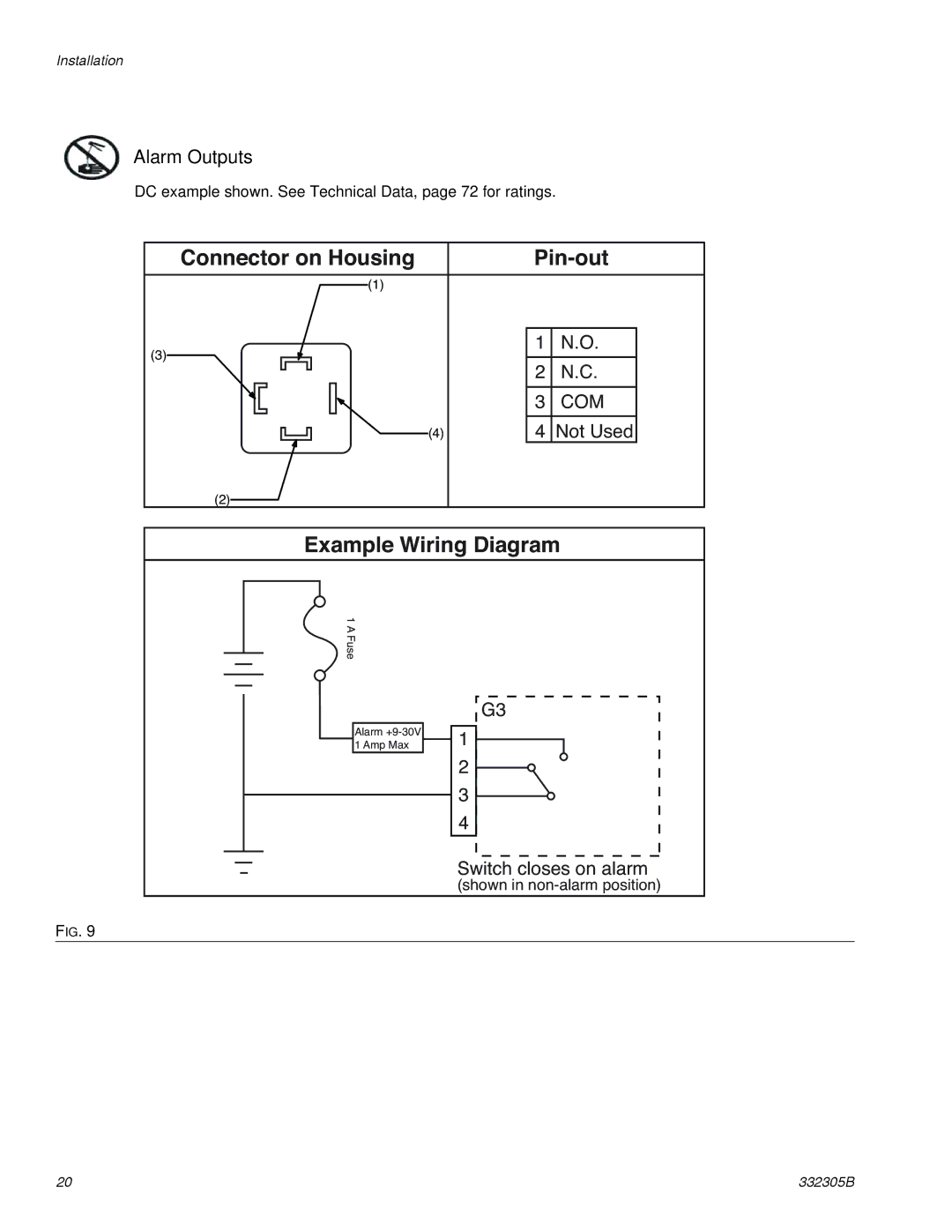
Alarm Outputs
DC example shown. See Technical Data, page 72 for ratings.
Connector on Housing |
| |||||||||
(1) |
|
|
| |||||||
|
|
|
|
|
|
|
|
|
|
|
(3) |
|
|
|
|
|
|
| 1 | N.O. |
|
|
|
|
|
|
|
|
|
|
| |
|
|
|
|
|
|
|
| 2 | N.C. |
|
|
|
|
|
|
|
|
|
| ||
|
|
|
|
|
|
|
| 3 | COM |
|
|
|
|
|
|
|
|
|
|
|
|
|
|
| (4) | 4 | Not Used |
| ||||
|
|
|
|
|
|
|
| |||
|
|
|
|
|
|
|
| |||
(2)
Example Wiring Diagram
1 A Fuse
Alarm
G3 |
1 |
2 |
3 |
4 |
Switch closes on alarm
(shown in
FIG. 9
20 | 332305B |