Installation
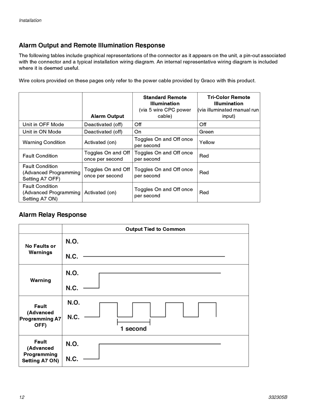
Alarm Output and Remote Illumination Response
The following tables include graphical representations of the connector as it appears on the unit, a
Wire colors provided on these pages only refer to the power cable provided by Graco with this product.
|
| Standard Remote | ||
|
| Illumination | Illumination | |
| Alarm Output | (via 5 wire CPC power | (via illuminated manual run | |
| cable) | input) | ||
|
|
|
| |
Unit in OFF Mode | Deactivated (off) | Off | Off | |
Unit in ON Mode | Deactivated (off) | On | Green | |
Warning Condition | Activated (on) | Toggles On and Off once | Yellow | |
per second | ||||
|
|
| ||
Fault Condition | Toggles On and Off | Toggles On and Off once | Red | |
once per second | per second | |||
|
| |||
Fault Condition | Toggles On and Off | Toggles On and Off once |
| |
(Advanced Programming | Red | |||
Setting A7 OFF) | once per second | per second |
| |
|
|
| ||
Fault Condition |
| Toggles On and Off once |
| |
(Advanced Programming | Activated (on) | Red | ||
per second | ||||
Setting A7 ON) |
|
| ||
|
|
|
Alarm Relay Response
Output Tied to Common
No Faults or | N.O. | ||||||
|
|
|
|
|
|
| |
Warnings | N.C. |
|
|
|
|
|
|
|
|
|
|
|
|
| |
|
|
|
|
|
|
|
|
| N.O. | ||||||
Warning |
|
|
|
|
|
|
|
| N.C. | ||||||
|
|
|
|
|
|
|
|
Fault | N.O. | ||||||
|
|
|
|
|
|
| |
(Advanced | N.C. |
|
|
|
|
| |
Programming A7 |
|
|
|
| |||
|
| ||||||
OFF) |
|
|
|
|
|
|
|
|
|
| 1 second | ||||
|
|
|
| ||||
|
|
|
|
|
|
|
|
Fault | N.O. | ||||||
(Advanced |
|
|
|
|
|
|
|
Programming | N.C. | ||||||
Setting A7 ON) | |||||||
12 | 332305B |