Installation
Wiring and Installation Diagrams
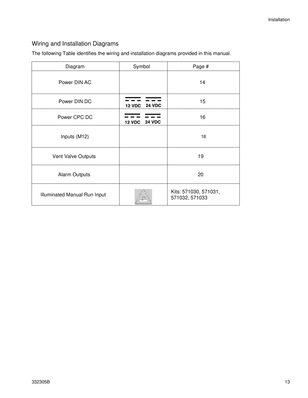
The following Table identifies the wiring and installation diagrams provided in this manual.
Diagram | Symbol | Page # |
|
|
|
Power DIN AC |
| 14 |
|
|
|
Power DIN DC |
| 15 |
|
|
|
Power CPC DC |
| 16 |
|
|
|
Inputs (M12) |
| 18 |
|
|
|
Vent Valve Outputs |
| 19 |
|
|
|
Alarm Outputs |
| 20 |
|
|
|
Illuminated Manual Run Input |
| Kits: 571030, 571031, |
| 571032, 571033 | |
|
| |
|
|
|
332305B | 13 |