Part / Model Numbers
Understanding the Model Number
Use the Code Sample provided below to identify each component’s location in the Model Number. The options for each component that make up the code are provided on the lists below.
NOTE: Some pump configurations are not available. Contact Graco Customer Service or your local Graco distributor for assistance.
| G 3 - G - |
|
|
|
|
| M |
| X |
|
|
|
|
|
|
|
|
|
|
|
|
|
|
|
|
|
|
|
|
|
|
|
|
|
|
|
| ||||||||
|
|
|
|
|
|
|
|
|
|
|
|
|
|
|
|
|
|
|
|
|
|
|
|
|
|
|
|
|
|
|
|
|
|
|
|
|
|
|
|
|
|
|
|
|
|
Code Sample: |
|
|
|
|
|
|
|
|
|
| a a b |
| b | - c c d e f f - g h i j k m n p | |||||||||||||||||||||||||||||||
G3 - G = Identifies pump as being a G3; G = Grease G3 - A = Identifies pump as being a G3; A = Oil
Code aa: Power Source
•12 = 12 Volts DC
•24 = 24 Volts DC
•AC = 100 - 240 Volts AC
Code bb: Operation Control
•MX = Max (Cycle) Control
Code cc: Reservoir Capacity (Liters)
•2L = 2 Liters
•4L = 4 Liters
•8L = 8 Liters
•12 = 12 Liters
•16 = 16 Liters
Code d: Follower Plate Installed
•F = Follower Plate Installed
•0 = No Follower Plate
DMSTM Models
h
g
i
j
Code e: Low Level Option
•L = Low Level with Controller
•0 = No Low Level monitoring
Code ff: Options
•00 = No Options
•03 = Powered Alarm Contact
•05 = 5 Pin CPC power cable
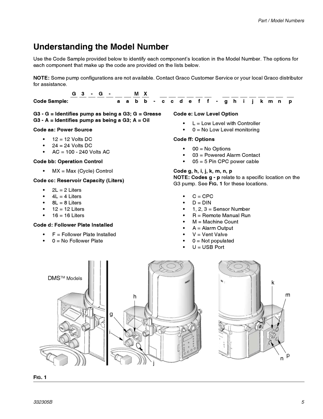
Code g, h, i, j, k, m, n, p
NOTE: Codes g - p relate to a specific location on the G3 pump. See FIG. 1 for these locations.
•C = CPC
•D = DIN
•1, 2, 3 = Sensor Number
•R = Remote Manual Run
•M = Machine Count
•A = Alarm Output
•V = Vent Valve
•0 = Not populated
•U = USB Port
k
m
n p
FIG. 1
332305B | 5 |