GR2K-GA-1002 Rev
Hitachi Gigabit Router GR2000 Series
Rev
GR2000 Installation Guide
GR2K-GA-1002
Release 4.00 May
Change Record
Preface
GateD
Acknowledgments
GR2K-GA-1002 Rev
Bsdi Internet Server
AT&T David M. GAY
Vii
INFO-ZIP Group
Viii
SUN MICROSYSTEMS, INC
Washington University in Saint Louis
Martin Birgmeier
Frank VAN DER Linden
Xii
Diff, grep
Xiii
Less
Tcpd
Tcpdump
Xiv
Traceroute
Apache Http server
Zlib
Xvi
Xntp Program
MD5 Program
Pimdd
Mrouted
Xviii
PIM sparse-mode pimd
Kame IPv6 Stack
Ltcs Label Traffic Control System
Abbreviations
DDP
Xxii GR2K-GA-1002 Rev
NIF
Xxiv GR2K-GA-1002 Rev
UNI
Xxvi
Damage to the equipment or a disruption in service
General Safety Guidelines
Xxviii
Specific Warning Instructions
Specific Caution Instructions
To avoid damage to the equipment or a disruption in service
Xxx
Cleaning
Other Instructions
Storage
Table of Contents
Network Interface Module NIF
RM-CPU2S
RMB-IOH
Routing Processor RP
Power Supply Unit POW
Customer-Responsibility Interface Cables
Xxxiii
MPLS/IP-VPN ROUTE-OS3
Configuration Limits
Xxxiv GR2K-GA-1002
Prerequisites
ATM Networking Restrictions
Segmentation/Topology Restrictions
LAN Networking Restrictions
WAN Networking Restrictions
Precautions on IP Connection with Other Devices
Precautions on IPX Connection
Xxxvi
Precautions for using Mpls
Precautions on Bridge Connections
Precautions on QoS Control
Precautions for using IP multicast
Layout
Power and Cooling Requirements
Xxxviii GR2K-GA-1002 Rev
Environmental Requirements
Handling of Gbic Connection of Setup Console
Routing and Connection of Cables
Mounting and Unmounting of Flash Memory Card MC
Fans
Starting, Setting Up, and Stopping
Introduction Supplied Media and Equipment Required
Expansion of Gbic Removal of Gbic
Xlii
GR2K-GA-1002 Xliii Rev
Outline of Installation
Xliv
RM-CPUMHRMB-CPU MH or RM-CPULHRMB-CPU LH Front Panel View
GR2K-GA-1002 Xlv Rev
100
101
102
Xlvi
Hardware Installation
GR2K-GA-1002 Xlvii Rev
Unmounting of MC Connection of Setup Console
Xlviii
Sequence of Device Operation
Specifications of Interface Cables and Connectors
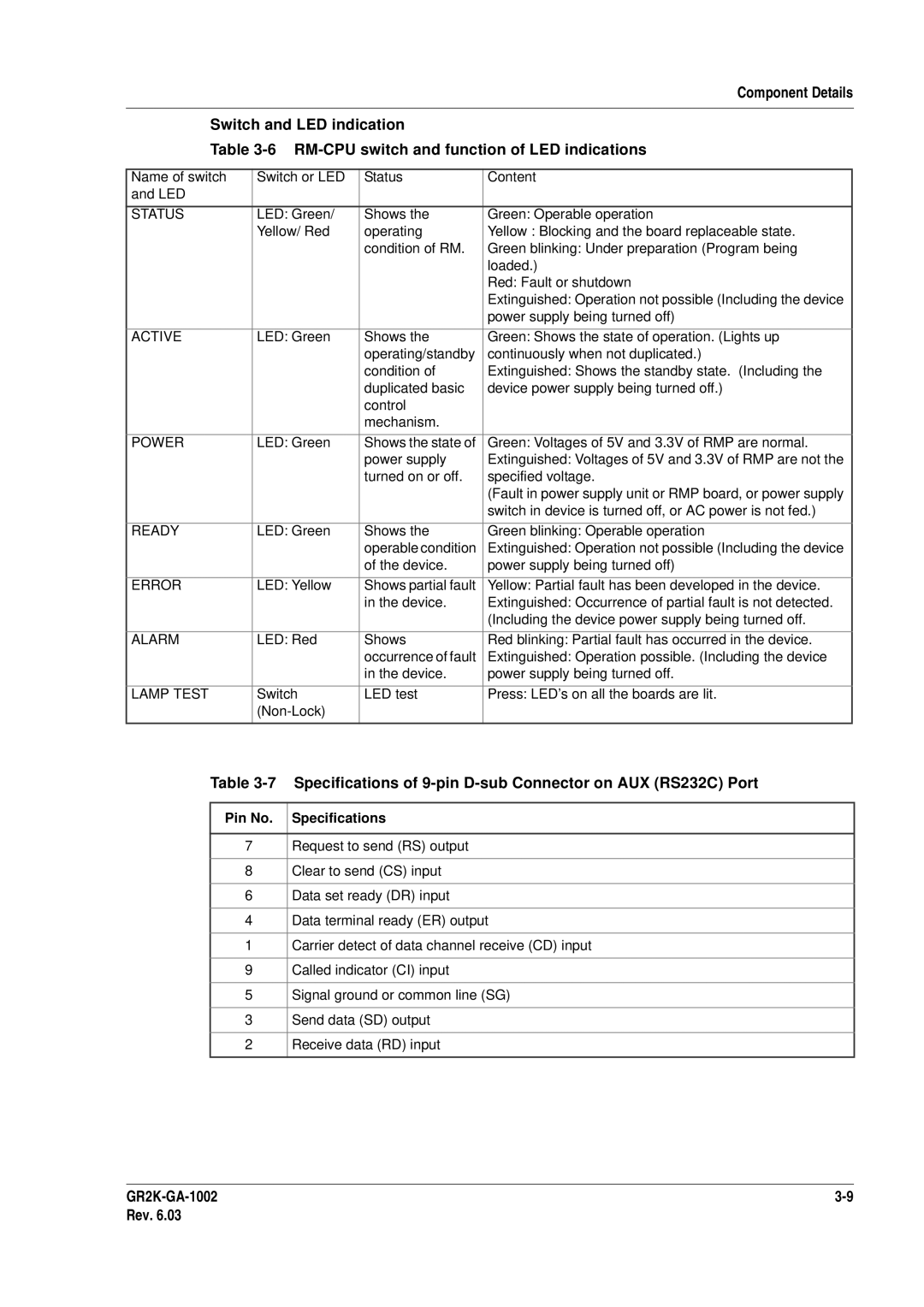
NE1G-1LHBA switch and function of LED indications
GR2K-GA-1002 Xlix Rev
LED indications
Modem setting RP mounting conditions by each model
This case core/clad diameter is 62.5/125 µm
Operation terminal conditions
Lii
Liii
Methods for Router Restart
Liv
Purpose and Organization of This Manual
Chapter General Information
Outline of Installation GR2K-GA-1002 Rev
Outline of Installation Process
Models
Chapter Product Overview
Front view of GR2000-2S AC input
Physical Appearance
FAN2
Product Overview
Front View of GR2000-4S AC Input
FAN3 RMP NIF1 NIF0
RM-CPU POW1 POW0
Rear View of GR2000-4S AC Input
POW1 POW0
Rear View of GR2000-6H AC Input
Front View of GR2000-10H with DC Input
Rear View of GR2000-10H with AC Input
10 Rear View of GR2000-10H with DC Input GR2K-GA-1002 Rev
11 Front View of GR2000-20H with AC Input GR2K-GA-1002 Rev
RP RP RP RP RP RM- RM- RP RP RP RP RP
12 Rear View of GR2000-20H with AC Input GR2K-GA-1002 Rev
13 Front View
GR2000-20H with DC Input
14 Rear View of GR2000-20H with DC Input GR2K-GA-1002 Rev
16 Rear View of GR2000-4 AC Input GR2K-GA-1002 Rev
15 Front View of GR2000-4 AC Input
18 Rear View of GR2000-10 with AC Input GR2K-GA-1002 Rev
17 Front View of GR2000-10 with AC Input
19 Front View of GR2000-10 with DC Input
IO0 IO1
CSW-1S CSW-1M CSW-0S CSW-0M
Placement of power supply units
23 Front View of GR2000-20 with DC Input GR2K-GA-1002 Rev
24 Rear View of GR2000-20 with DC Input GR2K-GA-1002 Rev
Guide rail attached Guide rail detached
Device Configuration
BCU POW
BCU RMP RM + RP
NIF
POW ATM WAN LAN
RMP NIF1 NIF0
GR2000 Installation Guide GR2000-2S
31 Front View of GR2000-4S
33 Front View of GR2000-6H
IO0
35 Front View of GR2000-10H with AC Input
37 Front View of GR2000-20H with AC Input GR2K-GA-1002 Rev
GR2000 Installation Guide GR2000-20H
38 Rear View of GR2000-20H with AC Input GR2K-GA-1002 Rev
BCU-M850H BCU-L850H
Device Components
Maximum Number of Device Components on Enhanced Models
BCU-H850H
BCU RM
Cabinet Network Processor Unit Chassis
Basic Control Unit BCU
BCU RM NIF
RMB-IO
RM-CPU
RM-IO
RMB-CPU
Routing Processor ModuleRP
Crossbar Switch CSW
RP-DV
GR2000 Installation Guide RP Specifications
RP name Specification
RP-A1
RP-D6
RP-C6
RP-CV
Network Interface Module NIF
List of NIF Modules
Type Module Name Interface Size
Product Overview List of NIF Modules
Flash Memory Card MC
Power Supply Unit POW
CPU Fan
Main Storage Card MS
Interface Cables
NIF accessory Gbic
Temperature monitoring sensor
GBIC-SX/LX/LH Physical Specifications Purchasing overseas
Software
Threshold value Temperature Significance Name Value
NIF
Interface Cables and Connectors
10 Specifications of Interface Cables and Connectors
Connections
POS MMF NWOC3C-2MD
NWMX1-4
BNC
NWE3-1C
1.1 LAN
Atmmmf
Atmsmf
1.2 WAN
Network Connections
1.3 ATM
LAN Connection
ATM Connection
WAN Connection
This page left intentionally blank
Cabinet Chassis
Installed Dimensions, Masses, and Minimum Service Clearances
Minimum Service Clearance for Desktop or Floor Installation
Component Details
Module Characteristics
Basic Control Unit BCU
RM-CPU2S
BCU Components
RMP Front Panel View GR2K-GA-1002 Rev
RMP 2S
Accesso
Power
Error
Alarm
Rest
Pin No Specifications
Line ERR
Lamp Test
RM-CPU4S, RMB-CPU 4S Front Panel View
Specifications of 9-pin D-sub Connector on AUX RS232C Port
Status
Active
10 RM-CPUS Front Panel View
RM-CPUS, RM-CPUM, RM-CPUMC2 and RM-CPUL
12 RM-IO4S Front Panel View
RM-IO4S, RMB-IO 4S and RM-IOH
EMA Suppress
RM Change
Reset
LINK/ACT
EMA Supress
RM-IOS, RM-IOM, and RM-IOL
Pin No. Specifications
RMB-IOH
8 CSW
CSW Status
Routing Processor RP
RP-A1/RP-D/RP-D6
12 RP Models
RP-C/RP-C6
21 RP-C/C6 Front Panel View Switch and LED indication
Network Interface Module NIF
15 NIF Models
Category Physical Interface NIF Name Board Size Remarks
1 NE100-8T, NE100-8TA and NE100-8TB
Component Details 15 NIF Models
Pin No
Connector Specifications
2 NE100-4F, NE100-4FS, and NE100-4FS4
Link
SIG-DT
Name Name of switch Status Content LED
Line
ACT
Name LED Color Status Content
NWVX-4
NE1G-1LB NE1G-1LHA
NWVX-4 Line LED indication
WAN 35-pin Male Connection Router 50-Pin Specifications
WAN 15-pin Male Connection Router 50-Pin Specifications
ACT, T/R
NWVX-8
Line state Detail of state State as seen by Sxmp MMI
Precautions when connecting NWVX-8
Line state
Indication
Line 5 Line 4 .+0#%6.+064 4 LINE8 1 8 Line 0 .+0
28 Line numbers for the cables attached to NWVX-8
DCE side GR2000 Cables attached to
28Connector Specifications for NWVX-8, Pin Assignment for
30Connector Specifications for NWVX-8, Pin Assignment for
Status Actg Line Erry T/R
Yellow Blocking and the board replaceable state
Line ERR ACT
NWJ1-8U physically appear as Figure
Status Link T/R Loop LOS RAI Line
Browser
Status Loop Link T/R LOS RAI Line
Line LOS RAI
ACT LOS AIS Line NWJ2-1U
State as seen by Line state
Line state Detail of state Indication in M
Browse
TR T Line ERR
Looped by rem
Line ERR Loop R ACT LOS RAI NWE3-2U
Line LOS RAI
LED Green
Name LED Color
Line RAI LOS
Status MST Line ERR ACT Link POS OC-3C/STM-1
Function of LED indication
Shows the operating Green Operable operation
NWOC3C-8S and NWOC3C-8M physically appear as Figure
MST Line ERR ACT Link Line 0A
NWOC12-4S and NWOC12-4M physically appear as Figure
46 NWOC48-1S, NWOC48-1S4 and NWOC48-1S8 Front Panel View
NWOC48-1A, NWOC48-1A4 and NWOC48-1A8
Indication
Status Green Yellow Extinguished
APS
48 NAOC3-1M and NAOC3-1S Front Panel View
Green blinking Under preparation Program being
LED Green Shows the operating
NAOC3-8S and NAOC3-8M physically appear as Figure
NAOC12-2S and NAOC12-2M physically appear as Figure
NE1G-4C physically appears as Figure
NWT3-1C physically appears as Figure
Line state Detail of state Indication in MMI
NWE1-8 physically appears as Figure
ACT
POW-M100H
87 POW Models
POW-S100S
POW-H100H
POW-LDC
Device Model Power Supply Configuration ’ty
POW-MDC
INPUT-MDC
POW-HDCH
56 Power Unit of POW-H100H
LED
LED
173 175
LED
SW1
POW-M100 and POW-L200
63 Power Unit of POW-S100
520
67 MC30 and MC64 Flash Memory Card Module
Fittings
3 V.24, V.35, and X.21 Interface Cables
69 WAN Loop Connector
Page
NWVX-4 NWVX-8
Pin high-density connect
74 Line numbers for the cables attached to NWVX-8
DCE side GR2000 Cables attached to
1m or shorter Coordinated individually
NWVX-8
Page
Router LAN setup boundary with network
Transmit + Receive + Unused
Core SC
Core SC
Boundary with network
UTP
POS SMF DSU
POS DSU
Customer facility
Carrier e.g., NTT facility
89 Connection to Device without Terminator
UTP Cable for Primary I.431 or I.431-a
Outer
91 Sample Indirect Connection with Primary I.431 or I.431-a
Pin No Function device side Function DSU side
Metal Coaxial Cable for Secondary G.703
95 Construction of duel shield type coaxial cable
Multimode Optical Fiber Cable for OC-3c/STM-1 POS MMF
Connector Attenuation 1 dB/km max km
Connector Attenuation 0.3 dB/km max km or 40 km
Page
DSU/ONU NAOC3-1M
Below
For connection to box
103 UTP Cable Specifications for 25Mbps ATM
Prerequisites
Local Setup Console and Remote Operation Terminal
Terminal type Connection patter Required function
Operation terminal conditions
RTS
GND
DCD
CTS
AT&W0
AT&Y0
Page
Page
1 RP
RP mounting conditions by each model
Model RP GR2000-2S GR2000-4S GR2000-6H GR2000-10H GR2000-20
Applicable Types and Quantities of RPs by Router Model
Model Mounting number
Whole RP
Quantities of NIFs by Router Model
10H
Inter Board
NAOC3-8S
NAOC12-2M
NAOC12-2S
NAOC3-8M
RP Memory Increment by RP Type
Resulting Memory Capacity MB
Add One MS64 Add One MS1
Router Model Max. No. of Lines Per NIF Per RP Per Router
Line Accommodation with WAN Other than Isdn and Overload
11 100BASE-FX Line Accommodation
6Mbit/s or less WAN circuit accommodation conditions
Condition Max. Throughput kbps per
Line Accommodation with WAN Overload
17 WAN Isdn Line Accommodation Limit Condition QoS
Max. Throughput kbps per RP
384 128 920 860 750
NIF
Condition Max. Aggregate Line Speed Mbps
Example a
Vrrp Mpls
Vlan Note Bridge Non-VLAN IP multicast IPv
Line accommodating conditions for ATM
Per router Per RP Per line
Vlan
Per RP Per Router
Maximum Number of ARP Entries
31 Maximum Number of ARP Entries
Router Model Maximum No. of ARP Entries
Maximum Number of Interfaces and Multihome Subnets
Maximum Number of Interfaces
Router Model Maximum Number of VCs Per Line Per NIF
36 Maximum Number of Neighbor Routers
Maximum Number of Neighbor Routers
BGP4
Memory Entries Multipath Not Used Multipath Used
Max. Limit
40 IP Multicast Accommodation Limits
42 Bridge Accommodation Limits
41 IPX Accommodation Limits
Maximum Limit Total Dynamic Static
44 Maximum Number of Dynamic and Static Entries
IP-VPN system
Parameter setting
NE1G-4C WAN NWVX-4 NWVX-8 NWJB-8 NWJ1-4U NWJ1-8U
Category NIF Name Mpls Support *1 Backbone circuit
NE1G-1LA NE1G-1SA NE1G-1LHA NE1G-1LHA8
NE1G-1LB NE1G-1SB NE1G-1LHBA
Memory Card Unit MC
Minimum Memory Requirements
NAOC3-8M NAOC3-8S
BGP4 Note
RIP+OSPF
Case of IPv4 multicast use
By protocols
IP unicast IP muiticast
Maximum path entry count
Maximum number of entries
Static Count
No.
Maximum number of entries ATM VCs By protocols
Entry Count
Entry Guara Count Entry count
Routing IP multicast path entry count
Processor IP unicast
Module Path entry Count per
LDP DU
Mpls protocol Function item Detailed item Support Mode
VPN ID
000/RP 10,000/device
Dynamic Entry and Static Entry Maximum Entry Count
55 Maximum entry number of Mpls policy
Maximum RP entry number Maximum device entry number
Memory size of 256 MB or greater
57 Cops agent accommodating conditions
RP-CRP-D
BCU
61 BCU minimum required memory
Number of NDP Entries
64 Number of interfaces
Number of Tunnel Interfaces
Maximum Number of IPv6 Addresses to be Set
Address
BGP4+
Tag-VLAN
Routing Processor Module RP and NIF
ARP
Router Model Number of Tag-VLAN Per RP Per Router
Number of Tag-VLANs to be Set in Multi-Home
76 Cops agent accommodating conditions
Items to be Prepared
Network Configuration
1 10BASE-T/100BASE-TX
2 100BASE-FX
3 1000BASE-SX/1000BASE-LX/1000BASE-LH
WAN Networking Restrictions
Packet Length
Protocol operation Terminal DTE
NTT
Device is Condition Alternative
Sync clock -clock
80 NWJ1-8U connection restrictions
Line Interface Time slots start Posible Time Number Slots
Isdn
Bandwidth Planning Considerations
Routing Capacity of GR2000 on ATM Interface
Cellularization Overhead
Own router
Transmission traffic by each service category
ITU-T
ATM Connection with Hitachi NP200 and NP220
LIF
Ilmi
CBR
Function-wise Conditions for ATM Connection
ATM Connection with IPX Devices
ATM Connection with Bridge Devices
Interface Address in Point-to-Point Line Connection
Page
Router a Path to Ia is to be Learned by IG P Xterna l peer
Page
Interface Address of Point-to-Point Type Line
Connection with IPv6 Router
13 Example for Specifying a nexthopself Parameter
Device Packet to Terminal Terminal a Terminal B
Page
Snmp
Functional item Detailed item
Configuration Settings
Setting of RIP Packet Processing
Setting of SAP Packet Processing
Serialization packet and diagnostic packet
Netbios packet
Use of NetWare
Model Traffic of Periodic SAP Packets
Spanning-Tree Protocol
Protocol and Topology Restrictions
LAN1
Bridge Definition on Isdn Interface
Relationship Between Load on RP and QoS
RP, NIF
Connection with LAN Switch
Tag-VLAN setting
Vlan type
21 Network Configuration
Common to protocols
Multicast relay
14.2 Redundant route route switching due to impediment
When using PIM-DM
14.2.2 When using Dvmrp
PIM-DM
Inapplicable network pattern
Redundant route exists
Tree type network
Page
Precautions for using Mpls
VPN
Versions prior to Ver
Contents of the TLV used
Page
Environmental Requirements
Temperature and Humidity
Dust
Dust Requirements
Computer Main Line Distribution Panel
Acoustic Noise
For the router
Input Power Requirements-AC Input
Input Power Requirements
100 Vac Single phase 50/60 Hz Ground Nema
CB Circuit breaker
Page
Router Model AC Input DC Input CB Type Phase Rating
Requirements for Circuit Breaker on Power Distribution Panel
Receptacle Types for AC Input
Page
Typical Power Consumption and Heat Dissipation Figures
Out lower rear end Out lower right side
12 Airflow of GR2000-4
Upper eft side Upper right side
Cooling Requirements for Rack-Mount Installation
Page
Chassis
Unpacking
When you handle this model
Packing list are obtained from the cargo
Carton Router chassis
Packing list are obtained from the cargo
Vinyl bag Router chassis Carton
Packing list are obtained from the cargo
Packing list are obtained from the cargo
RM/RP/NIF full size board Carton Polyethylene or vinyl bag
Memory module Polyethylene or vinyl bag Carton
13 Unpacking of Separately Shipped Cable
Handling of Components Subject to Static Electricity
Allowable Style of Installation by Router Model
GR2000-2S GR2000-4
17 Desktop Installation for GR2000-6H
Floor Installation of Chassis
Page
Page
Screwjack/earthquake-proof bolt hole M12
Screw jack Caster
Page
Screwjack
Page
Stopper nut 10 mm
Page
Page
Guide rail M5 screw x
Screw
Chassis
Page
30600 RearFront
Chassis AC Input
Inch Rack GR2000-10H or GR2000-10 Guide Rail
Removing
Page
Chassis
Cable Power Interfa cable Guide rail
Page
547.95 133.35 177.8 1430
Open rack
Inch Rack GR2000-20H or GR2000-20 Guide Rail
General Rules for Routing and Connection of Cables
Page
Page
Page
Rear
2.1 GR2000-2S
Power Switch
Tighten the screws
Front
Page
200V AC Input
2.5 GR2000-20H
Front
Page
2.6 GR2000-4
53 Terminal Board/Wire Dimensions for DC Input to GR2000-20H
Front
Page
Front
Front
Page
Connection of Interface Cables
60 Terminal Board/Wire Dimensions for DC Input to GR2000-20
WAN V.24, V.35,
Cause malfunction or a failure
RJ-48 to the mating receptacle on the own router
SC 2-core When removing, just pull
Mating receptacle on the own router
70 illustrates how to unmount an MC
How to remove
BCU RM, duplexed
Console specifications
Overview of Device Operation
Starting, Setting Up, and Stoppin
Switch fully until it stops
Pause at least 2 seconds before you turn on the power
Password noneoperator
Page
BCU, RP, and NIF Modules
Adding and Removing Component
Page
Page
Guide rail Anchor screw
1 GR2000-4S
Below with both hands when installing or removing
Below with both hands when installing or removing
Input Unit AC or DC
Follow the instructions illustrated in Figure
Input Unit AC or DC
Follow the instruction illustrated in Figure
Power Switch
POW for AC Input
POW
Dju st th e p ro je ctio n s
POW
Fan Tray for GR2000-10H
Fan tray Cover
RM-CPU
Addition/Removal of Main Memory Module for RM BCU
Installed connector
For termination of duplex mode
Removingconfigmodeseta BCU duplexCR
Network Interface NIF
Adding an RP
Removing an RP FreerprpnoCR
Page
Introduction
Software Installation and Update