Hardware Maintenance Manual
Page
Hardware Maintenance Manual
Page
About this manual
Important Safety Information
About this manual
Page
For Information About See Publication
Related Publications
Page
Contents
Types 6058/6059/6269/6578/6579
Related Service Information 185
Page
Run Setup
Diagnostic Error Code FRU/Action
Reboot the system
No action
Go to the ″Undetermined problems″ section
Connected and/or enabled
Information
Press F3 to review the log file
Adapter card
Power-off/on system and re-test
001-260-XXX System board
001-254-XXX System board 001-255-XXX 001-256-XXX
Device on IRQ1
Device on IRQ2
Battery
Run Setup and re-test
005-00X-XXXVideo error Video card, if installed
005-010-XXX Video card, if installed 005-011-XXX
Video cable
Diskette drive Cable
005-2XX-XXX Video card, if installed
Remove external serial device, if present
011-002-XXX System board
Run Setup, enable port
Diagnostic Error Code FRU/Action 011-013-XXX System board
Wrap plug
011-03X-XXX System board
014-03X-XXX System board
Diagnostic Error Code FRU/Action 014-013-XXX System board
014-2XX-XXX External parallel device
Remove USB devices and re-test
Run setup and check for conflicts
PCI card
Riser card, if installed
025-02X-XXX IDE signal cable 025-03X-XXX
025-00X-XXX IDE signal cable
020-262-XXX PCI card
025-000-XXX No action
030-03X-XXX Scsi signal cable
030-00X-XXX Scsi signal cable
RAID signal cable
Speakers
071-02X-XXX
Remove the game port device and re-test
System
Mouse
Microprocessors
Flash the system and re-test
Flash system
Voltage Regulator Module VRM
170-250-XXX Power supply
175-250-XXX Check fans
Assure Asset Security Enabled
Replace the memory module called out by
Test
Run Setup to enable DDC
XXX-XXXMouse error
XXX-XXXModem error Remove the Modem and re-test the system
217-28X-XXX Hard Disk Drive Cable
Types 6568/6569/6648/6649
Page
Security
Product description
Specifications Types 6568/6569/6648/6649
Specifications Information ISO/ANSI
Airflow
Feature Description Electrical Input
Acoustical Noise Emission
Values
General checkout
Set Power-On Self-Test to Enhanced
Did YOU Receive the Correct RESPONSE?
Module test menu and hardware configuration report
Printer
Keyboard
Power Cord
Power supply
Power-on Switch
Check/Verify FRU/Action
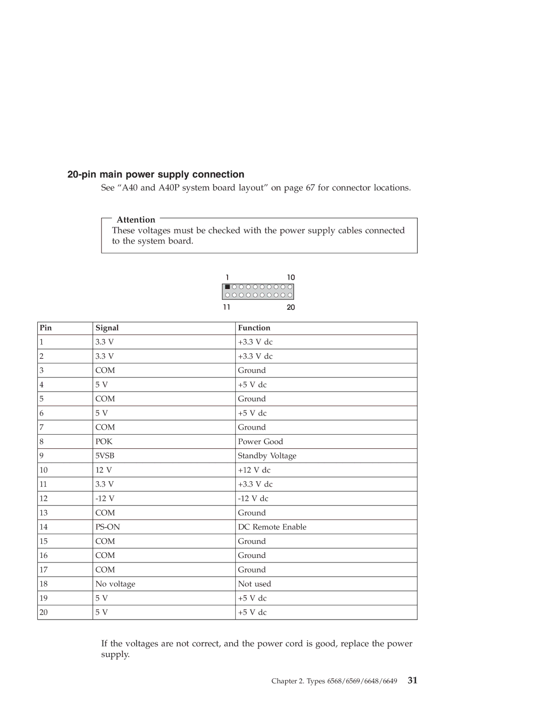
Pin Signal Function
Pin main power supply connection
Display
Diagnostics, test and recovery information
Power-On Self-Test Post
Post beep codes
Product Recovery Program menu
Error code format
Enhanced Diagnostics download or diskette
IBM PC Enhanced Diagnostics
Running diagnostics tests
Navigating through the diagnostics programs
IBM PC Enhanced Memory Diagnostics
Test selection
Alert-On LAN test
Asset ID test
Test results
IBM Fixed Disk Optimized Test
Hard file Smart test
Quick and Full erase hard drive
Select Fixed Disk Optimized Test
SIMM/DIMM/RIMM memory errors
Asset Eeprom backup
Iomega Zip drive test
Viewing the test log
Setup Utility program
Hard disk drive boot error
When to use the Low-Level Format program
Cause Action
Preparing the hard disk drive for use
Additional service information
Replacing a system board
Replacing a processor
Passwords
Security features
Management Information Format MIF
Vital product data
Alert on LAN
Hard disk drive jumper settings
Bios levels
CD-ROM drive jumper settings
Flash recovery boot block jumper
Flash BIOS/VPD update procedure
Power management
Automatic configuration and power interface Acpi Bios
Advanced Power Management
Automatic Hardware Power Management features
Setting Automatic Hardware Power Management features
Level
Automatic Power-On features
Network settings
Wake on LAN
Flash over LAN update POST/BIOS over network
System board memory
Supported memory configuration
Computer exploded view Types 6568/6569/6648/6649
Computers Memory Module Size Speed Type
Input/Output connectors
Replacing the cover
Cover removal
EMC shield system board
EMC shield CD-ROM drive bay
Adapter slots
Installing adapters
CD-ROM drive removal and replacement
Types 6568/6569/6648/6649
Page
″ drive removal
Internal drive removal
Hard drive removal
Fan/speaker bracket removal
Components of the riser card
Power supply removal
PCI slot Ethernet disable jumper
A40/A40P System board jumper settings
A40/A40P Clear CMOS/Flash Boot Block Recovery
A40 and A40P system board layout System board locations
A40/ A40P Processor Speed Settings
A40/A40P Diskette Write Access
Jumper Setting Description
Symptom-to-FRU index
Beeps Description
Beep symptoms
Beep Symptom FRU/Action Run Setup
See System board memory on
Keyboard stuck key?
Post error codes
No-beep symptoms
Symptom/Error FRU/Action
See Undetermined problems on
Run Setup and verify Configuration
Post Error Code FRU/Action 106 System Board
Reseat adapters
Adapter Memory
Page
5XX
Run Setup and verify diskette configuration
Post Error Code FRU/Action 602 Bad Diskette?
Settings
Run Configuration
Types 6568/6569/6648/6649
Page
BSC Adapter
Post Error Code FRU/Action
21XX Scsi Device
Display
Page
Types 6568/6569/6648/6649
Page
Types 6568/6569/6648/6649
16500 Tape Attachment
Post Error Code FRU/Action 164XX MB Internal Tape Drive
16520 Streaming Tape Drive
166XX Token Ring Adapter
Rotary Switch Circuit Board
Post Error Code FRU/Action 20104 Memory Module DRAM, Vram
20105 to Printer/Scanner Option
Replace memory module shown in graphic
Page
Miscellaneous error messages
Check power supply and signal cable
Connections to network adapter
Run the Memory tests
If network administrator is using Lccm
Rerun the Fixed Disk diagnostic. If
Remove the first drive that does not show up
Remaining drives then show up, replace
External Device Self-Test OK?
Undetermined problems
Model
Model tables Country/Region/Language
North America Model
Latin America Model
Parts Types 6568/6569/6648/6649
Index System Types 6568/6569/6648/6649 FRU No
Parts listing
″D0″ Step Level Flip Chip with Heatsink 09N4373 Note
Keyboards 6568/6569 PCNext Lite Pearl White
37L2579
Keyboards 6648/6649 PCNext Lite Black
37L2580
Computer Power Cords
Special tools
Display and Monitor Information
Types 6058/6059/6269/6578/6579
Page
Types 6058/6059/6269/6578/6579
705 BTU/hr watts
Specifications Types 6058/60596269/6578/6579
Maximum 0.30 kVA as shipped
General checkout
Did YOU Receive the Correct RESPONSE?
Module test menu and hardware configuration report
Keyboard
Correct the voltage-selector switch setting
Pin main power supply connection
Display
Diagnostics, test and recovery information
Post beep codes
IBM PC Enhanced Diagnostics
Navigating through the diagnostics programs
IBM PC Enhanced Memory Diagnostics
Function Code
Hard file Smart test
Page
Quick and Full erase hard drive
Asset Eeprom backup
SIMM/DIMM/RIMM memory errors
Setup Utility program
Hard disk drive boot error
Additional service information
Replacing a processor
Passwords
Vital product data
Hard disk drive jumper settings
Primary Master Secondary Slave 40X 48X
Flash BIOS/VPD update procedure
Flash recovery boot block jumper
Automatic Hardware Power Management features
Network settings
Flash over LAN update POST/BIOS over network
System board memory
Computer exploded view Types 6058/6059/6269/6578/6579
Input/Output connectors Type
Input/Output connectors Types 6058/6059/6578/6579
Replacing the cover
EMC shield front
Air duct Types 6058/6059/6278/6279
CD-ROM drive removal
Hard drive removal
Power supply removal
Lift out the power supply
A20 System board jumper settings
A20 Clear CMOS/Flash Boot Block Recovery
A20 system board layout Type System board locations
A20 Diskette Write Access
A20 Processor Speed Settings
A40/A40P System board jumper settings
A40/A40P Processor Speed Settings
Symptom-to-FRU index
Use the following table to diagnose beep symptoms
Beep Symptom FRU/Action
Post error codes
Memory size change. SeeSetup Utility
131
17X C2 Security
Types 6058/6059/6269/6578/6579
Post Error Code FRU/Action 301 Keyboard
601 Diskette Drive a
602 Bad Diskette?
1047 Bit AT Fast Scsi Adapter
Check Scsi terminator installation
1101, 1102, 1106, 1108 System Board
1107 Communications Cable
Page
209X Diskette Drive
Page
Types 6058/6059/6269/6578/6579
Page
Types 6058/6059/6269/6578/6579
185XXXX
Post Error Code FRU/Action 20104 Memory Module DRAM, Vram
Page
Miscellaneous error messages
Setup/Configuration. See Setup Utility
See Printer on
Page
Undetermined problems
Model tables Country/Region/Language
Parts Types 6058/6059/6269/6578/6579
Dasd Bracket
Index System Types 6058/6059/6269/6578/6579 FRU No
VDA, VEA,VFJ,VGJ Dasd Rail KIT
THA, THT, THC, THM, THV, THD, THJ, VDJ, VEJ, VFM, VFD, VGG
RBA,RCG,TEG,VDA,VEA,VFJ,VGJ AIR Baffle Duct
″ Dasd Bracket Handle
HDU, ADU, UDU, VDU, KDS, KES, HEG, ACG, UCG, D4S, KCS, KAS
THT, THC, THM, THV, THD, THJ, VDJ, VEJ, VFM, VFD, VGG, VGC
Keyboards PCNext Lite Pearl White
14F0033
Recovery CDs
Special tools
Page
General safety
Safety information
Electrical safety
Related Service Information
Safety inspection guide
Safety notices multi-lingual translations
Handling electrostatic discharge-sensitive devices
Grounding requirements
Page
To Connect To Disconnect
Do not
Statement
Use safe practices when lifting
Perigo
Para Conectar Para Desconectar Desligue Tudo
Cuidado
Perigo
Ao levantar a máquina, faça-o com segurança Instrução
Page
Related Service Information
Page
Related Service Information
Page
Related Service Information
Page
Related Service Information
Connexion Déconnexion Mettez les unités hors tension
Related Service Information
Faites-vous aider pour soulever ce produit
Vorsicht
Kabel anschlieβen Kabel l÷sen
Achtung
Vorsicht
≥ 32 kg 70.5 lbs ≥ 55 kg 121.2 lbs
Pericolo
Per collegare Per scollegare
Attenzione
Attenzione
Pericolo
Attenzione
Attenzione
Page
Related Service Information
Importante
Para la conexin Para la desconexiín
Peligro
Precaución
≥ 32 kg 70.5 lbs ≥ 55 kg 121.2 lbs
Fuente de alimentaciín Declaración
Send us your comments
Problem determination tips
Page
Term Information
Trademarks
Cdpd
NMI
Page
Page
Part Number 06P1504