Thermal/Mechanical Reference Design
A potential mechanical solution for heavy heatsinks is the direct attachment of the heatsink to the chassis pan. In this case, the strength of the chassis pan can be utilized rather than solely relying on the baseboard strength. In addition to the general guidelines given above, contact with the baseboard surfaces should be minimized during installation in order to avoid any damage to the baseboard.
The Intel reference design for
2.2Processor Thermal Parameters and Features
2.2.1Thermal Control Circuit and TDP
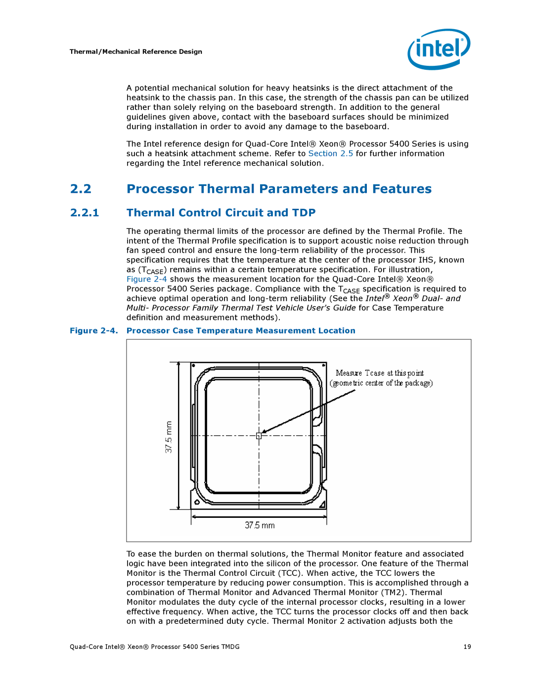
The operating thermal limits of the processor are defined by the Thermal Profile. The intent of the Thermal Profile specification is to support acoustic noise reduction through fan speed control and ensure the
Figure 2-4. Processor Case Temperature Measurement Location
To ease the burden on thermal solutions, the Thermal Monitor feature and associated logic have been integrated into the silicon of the processor. One feature of the Thermal Monitor is the Thermal Control Circuit (TCC). When active, the TCC lowers the processor temperature by reducing power consumption. This is accomplished through a combination of Thermal Monitor and Advanced Thermal Monitor (TM2). Thermal Monitor modulates the duty cycle of the internal processor clocks, resulting in a lower effective frequency. When active, the TCC turns the processor clocks off and then back on with a predetermined duty cycle. Thermal Monitor 2 activation adjusts both the
19 |