Thermal/Mechanical Reference Design
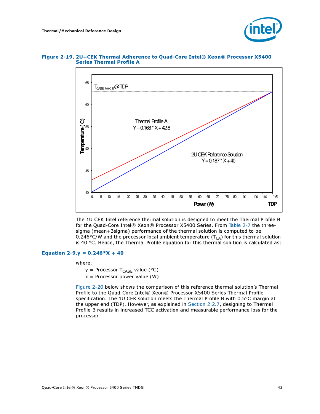
Figure 2-19. 2U+CEK Thermal Adherence to Quad-Core Intel® Xeon® Processor X5400 Series Thermal Profile A
| 65 | TCASE_MAX_B@ TDP |
|
|
|
|
|
|
|
|
|
|
|
|
|
|
|
| |||
| 60 |
|
|
|
|
|
|
|
|
|
|
|
|
|
|
|
|
|
|
|
|
C) |
|
|
|
|
| Thermal ProfileA |
|
|
|
|
|
|
|
|
|
|
|
| |||
( | 55 |
|
|
|
| Y =0.168* X +42.8 |
|
|
|
|
|
|
|
|
|
|
|
| |||
Temperature |
|
|
|
|
|
|
|
|
|
|
|
|
|
|
|
| |||||
50 |
|
|
|
|
|
|
|
|
|
|
|
|
|
|
|
|
|
|
|
| |
|
|
|
|
|
|
|
|
|
|
| 2U CEK ReferenceSolution |
|
|
|
| ||||||
|
|
|
|
|
|
|
|
|
|
|
|
|
|
|
| ||||||
|
|
|
|
|
|
|
|
|
|
|
|
| Y =0.187* X +40 |
|
|
|
| ||||
| 45 |
|
|
|
|
|
|
|
|
|
|
|
|
|
|
|
|
|
|
|
|
| 40 |
|
|
|
|
|
|
|
|
|
|
|
|
|
|
|
|
|
|
| 120 |
| 0 | 5 | 10 | 15 | 20 | 25 | 30 | 35 | 40 | 45 | 50 | 55 | 60 | 65 | 70 | 75 | 80 | 90 | 100 | 110 | |
|
|
|
|
|
|
|
|
|
|
|
|
| Power (W) |
|
|
|
|
|
| TDP | |
The 1U CEK Intel reference thermal solution is designed to meet the Thermal Profile B for the
Equation 2-9.y = 0.246*X + 40
where,
y = Processor TCASE value (°C) x = Processor power value (W)
Figure 2-20 below shows the comparison of this reference thermal solution’s Thermal Profile to the Quad-Core Intel® Xeon® Processor X5400 Series Thermal Profile specification. The 1U CEK solution meets the Thermal Profile B with 0.5°C margin at the upper end (TDP). However, as explained in Section 2.2.7, designing to Thermal Profile B results in increased TCC activation and measurable performance loss for the processor.
43 |
