Heatsink Clip Load Methodology
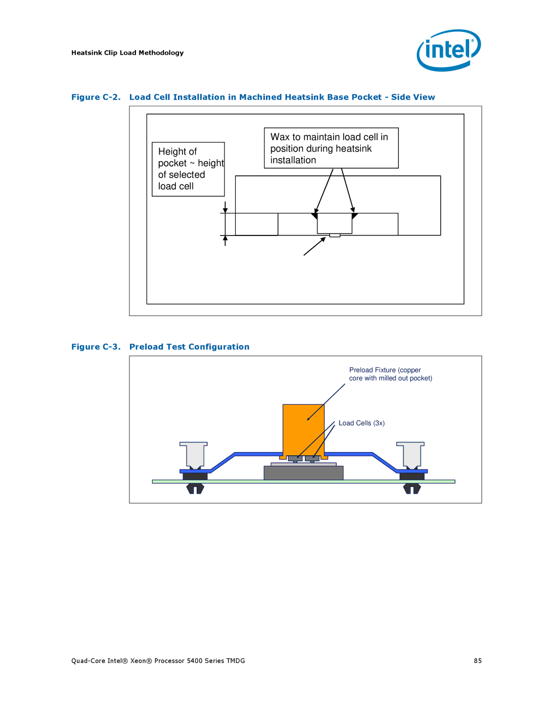
Figure C-2. Load Cell Installation in Machined Heatsink Base Pocket - Side View
Height of pocket ~ height of selected load cell
Wax to maintain load cell in position during heatsink installation
Figure C-3. Preload Test Configuration
Preload Fixture (copper |
core with milled out pocket) |
Load Cells (3x) |
85 |