GD82559ER — Networkin g Silicon

Symbol

Type


Name and Function


Flash Address[13]/EEPROM Data Input. During Flash accesses,

FLA[13]/

OUT

this multiplexed pin acts as the Flash Address [13] output signal.

EEDI

During EEPROM accesses, it acts as serial output data to the


EEPROM Data Input signal.


FLA[12:8]

OUT

Flash Address[12:8]. These pins are used as Flash address outputs

to support 128 Kbyte Flash addressing.


Flash Address[7]/Clock Enable. This is a multiplexed pin and acts


as the Flash Address[7] output signal during nominal operation. When

FLA[7]/

T/S

the PCI RST# signal is active, this pin acts as input control over the

CLKENB

FLA[16]/CLK25 output signal. If the FLA[7]/CLKEN pin is connected to


a pull-up resistor (3.3 KΩ), a 25 MHz clock signal is provided on the


FLA[16]/CLK25 output; otherwise, it is used as FLA[16] output.


FLA[6:2]

OUT

Flash Address[6:2]. These pins are used as Flash address outputs

to support 128

Kbyte Flash addressing.


Flash Address[1]/Auxiliary Power. This multiplexed pin acts as the


Flash Address[1] output signal during nominal operation. When RST is

FLA[1]/

T/S

active (low), it acts as the power supply indicator. If the 82559ER is fed

AUXPWR

PCI power, this pin should be connected to a pull-down resistor; if the


82559ER is fed by auxiliary power, this pin should be connected to a


pull-up resistor.


FLA[0]

T/S

Flash Address [0]. This pin acts as the Flash Address[0] output

signal during nominal operation.


EECS

OUT

EEPROM Chip Select. The EEPROM Chip Select signal is used to

assert chip select to the serial EEPROM.


FLCS#

OUT

Flash Chip Select. The Flash Chip Select signal is active during

Flash.


FLOE#

OUT

Flash Output Enable. This pin provides an active low output enable

control (read) to the Flash memory.


FLWE#

OUT

Flash Write Enable. This pin provides an active low write enable

control to the Flash memory.


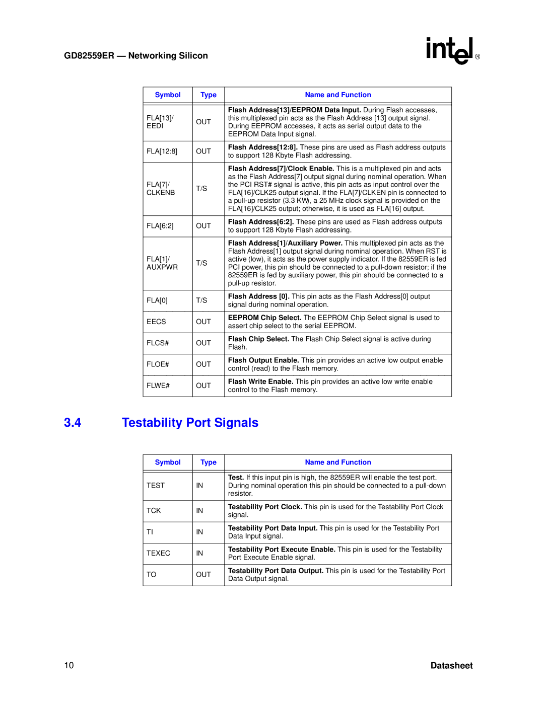
3.4Testability Port Signals

Symbol

Type

Name and Function


TEST

IN

Test. If this input pin is high, the 82559ER will enable the test port.

During nominal operation this pin should be connected to a pull-down


resistor.


TCK

IN

Testability Port Clock. This pin is used for the Testability Port Clock

signal.


TI

IN

Testability Port Data Input. This pin is used for the Testability Port

Data Input signal.


TEXEC

IN

Testability Port Execute Enable. This pin is used for the Testability

Port Execute Enable signal.


TO

OUT

Testability Port Data Output. This pin is used for the Testability Port

Data Output signal.


10

Datasheet

Page 16
Image 16
Intel GD82559ER manual Testability Port Signals

GD82559ER specifications

The Intel GD82559ER is a highly regarded network interface controller (NIC) designed for use in various computing environments, primarily for stable connectivity in both desktop and server applications. Released as part of the 82559 family of Ethernet controllers, the GD82559ER features advanced technologies that enhance performance, reliability, and manageability.

One of the standout features of the 82559ER is its ability to support both 10/100 Mbps Ethernet. This dual capability allows the controller to operate in a wide range of network settings, making it adaptable to legacy systems while also providing support for modern Ethernet standards. This versatility is crucial for organizations looking to maintain operational effectiveness without the need for immediate upgrades to their existing infrastructure.

The GD82559ER employs a PCI interface, which allows it to connect with various devices and motherboards easily, making it a go-to choice for manufacturers aiming for integration in their systems. It also includes features like Auto-Negotiation, enabling the NIC to automatically detect and select the appropriate speed and duplex mode for optimal performance. This capability is essential in dynamic networking environments, where devices from various generations coexist.

Power management is another critical aspect of the GD82559ER. The controller supports advanced power-saving features like PCI Power Management, reducing energy consumption during low-usage periods. This not only contributes to lower operational costs but also aligns with modern eco-friendly initiatives in technology.

Additionally, the GD82559ER comes equipped with advanced diagnostics and monitoring capabilities. This enhances the network's manageability by allowing administrators to track performance metrics and diagnose issues effectively. Through its onboard diagnostics, the controller aids in ensuring a stable network connection, allowing for timely interventions when issues arise.

The controller is also designed with a robust architecture that supports various operating systems, facilitating a broad implementation across different platforms. As a result, the GD82559ER has become a reliable option for system builders and enterprises focused on building dependable networking solutions.

Overall, the Intel GD82559ER is a versatile, high-performance network interface controller that continues to serve as a foundational component for computer systems that require efficient, reliable networking capabilities. Its combination of technologies and features makes it a popular choice in diverse computing environments.