Intel MCS-80/85 manual Additional 808SA Interrupts

Models: MCS-80/85

1 210
Download 210 pages 34.15 Kb
Page 148
Image 148

MCS-85™ APPLICATIONS

Basic operation, for a block move, is that the CPU loads the 8257 with the starting address of the source block and the length * of the block in- to Channel O. Channel 1 is programmed with the starting location of the destination block and the length. A bit in Port C of the 8255 is set by the CPU which initiates a DMA request on Channels 0 and 1. Because the 8257 is initial- ized to the rotating priority mode, the first DMA cycle is from Channel 0 which latches the data from the'first location of the source block into the 8212. The second cycle will be from Channel 1 which will store the latched data into the first location of the destination block. The next cycle will return to Channel 0 and the sequence will start over again until the length (terminal count) is reached. Programming the 8257 stop bit in- sures that each channel will be disabled when its respective terminal count is reached.

This configuration also supports a block fill. DMA Channel 0 point.s to a location containing the fill value and has a length of one. Channel 1 points to the starting location of the destination block and contains the length. When the se- quence is initiated the value will be loaded into the latch by Channel O. Channel 0 reaches TC and is disabled. Priority rotates to Channel 1 which will repeatedly write into the destination block the value stored in the latch until TC is reached.

Block search operations use the 8-bit compara- tor and Ports A & B of the 8255 and Channel 2 of the 8257. The CPU loads Port B with the search value and the DMA channel with the search area (starting address and length). A Port C bit initiates the DMA READ r~quest. Channel 2 DMA Acknowledge sets Port A of the 8255 up as the receiver for the DMA READ cycle by multiplexing Ao, A1 , and CS. Each cycle of the DMA then loads Port A with the value of the

-(The value loaded into the low-order 14-bits of the terminal count register specifies the number of DMA cycles minus one before the Terminal Count (TC) output is activated. For instance, a terminal count of 0 would cause the TC output to be active in the first DMA cycle for that channel. In general, if Length = the number of desired DMA cycles, load the value Length-1 into the low-order 14-bits of the terminal count register.)

pointed-to location in the block. When Port A equals Port B, the output of the cqmparator will gate off the DMA request. The requesting pro- gram can now read the Channel 2 address which is pointing to the search value plus one. However, if the status register of the 8257 in- dicates that TC of Channel 2 has been reached, then no match was found.

RST 7

On the 8080Al8228 system if one tied INTA out of the 8228 to + 12 volts through a 1KO resistor, the 8228 would generate a RST 7 instruction to the 8080A upon interrupt. This was a very inex- pensive mechanism.

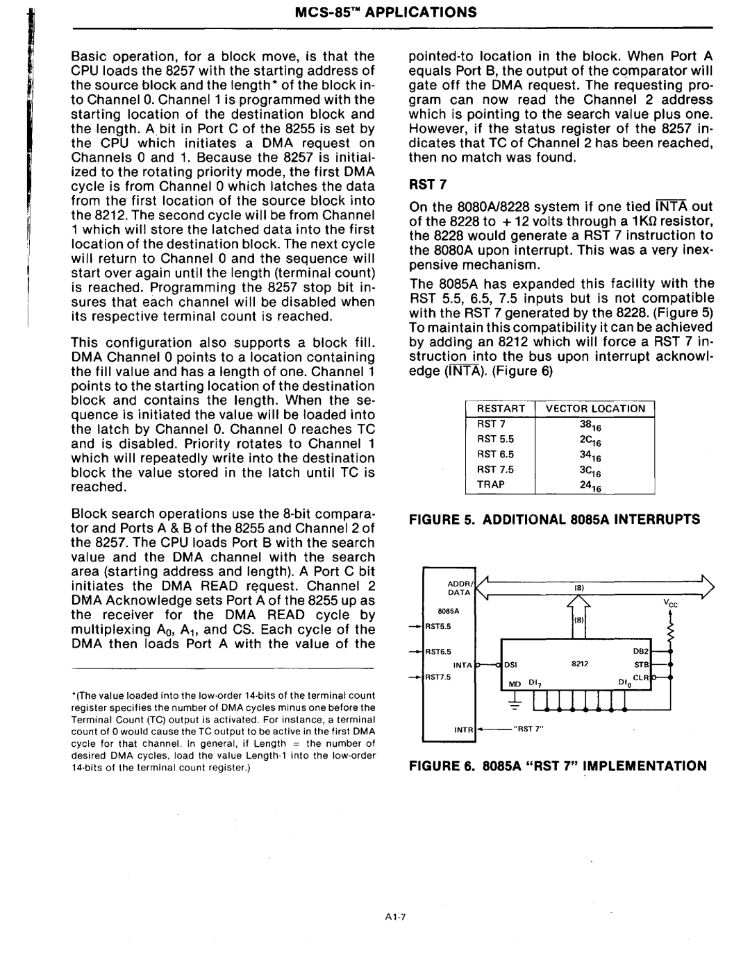
The 8085A has expanded this facility with the RST 5.5, 6.5, 7.5 inputs but is not compatible with the RST 7 generated by the 8228. (Figure 5) To maintain this compatibility it can be achieved by adding an 8212 which will force a RST 7 in- struction into the bus upon interrupt acknowl- edge (INTA). (Figure 6)

RESTART

VECTOR LOCATION


RST 7

38'6


RST 5.5

2C'6


RST 6.5

34'6


RST 7.5

3C'6

TRAP

24'6


FIGURE 5_ ADDITIONAL 808SA INTERRUPTS

DB2

STB

-RST7.5

INTR - "RST7"

FIGURE 6. 808SA "RST 7" IMPLEMENTATION

A'-7

Page 148
Image 148
Intel MCS-80/85 manual Additional 808SA Interrupts

MCS-80/85 specifications

The Intel MCS-80/85 family, introduced in the late 1970s, is a seminal collection of microprocessors that played a pivotal role in the early days of computing. The MCS-80 series, initially targeting embedded systems and control applications, gained remarkable attention due to its innovative architecture and flexible programming capabilities.

The MCS-80 family is anchored by the 8080 microprocessor, which was one of the first fully integrated 8-bit microprocessors. Released in 1974, the 8080 operated at clock speeds ranging from 2 MHz to 3 MHz and featured a 16-bit address bus capable of addressing up to 64KB of memory. The processor’s instruction set included around 78 instructions, providing extensive capabilities for data manipulation, logic operations, and branching.

Complementing the 8080 was a suite of support chips, forming the MCS-80 platform. The most notable among them was the 8155, which integrated a static RAM, I/O ports, and a timer, tailored for ease of designing systems around the 8080. Other support chips included the 8085, which provided improvements with an integrated clock generator, making it compatible with more modern designs and applications.

The MCS-85 series, on the other hand, revolves around the 8085 microprocessor, which provided a more advanced architecture. The 8085 operated at clock speeds of up to 6 MHz and came with a 16-bit address bus, similar to its predecessor. However, it introduced more sophisticated features, including an enhanced instruction set and support for interrupt-driven programming. These enhancements made the 8085 especially appealing to developers working in real-time processing environments.

The MCS-80/85 family utilized NMOS technology, known for its lower power consumption and higher performance compared to previous technologies like TTL. The family’s architecture allowed for easy interfacing with a variety of peripherals, making it a favorite for educational institutions and hobbyists embarking on computer engineering projects.

With its robustness, versatility, and affordability, the Intel MCS-80/85 microprocessors laid the groundwork for many subsequent microcomputer systems and applications. The legacy of this powerful family continues to influence modern microprocessor design, emphasizing the importance of reliable architecture in a rapidly evolving technology landscape.