Owner’s Guide
Display & Media Center
LT-3280/LT-3780
LCD Flat Panel HDTV
MODEL NUMBER LT-3280/LT-3780 Flat Panel HDTV DISPLAY SERIAL NUMBER
For Your Records
MEDIA CENTER SERIAL NUMBER PURCHASE DATE DEALER NAME STREET ADDRESS
CITYSTATEZIP PHONE
Chapter 2 Connecting
Contents
Important Information
Chapter 1 Product Overview
Chapter 5 Using the TV Menu
Chapter 3 NetCommand Setup and Editing
Chapter 4 IEEE 1394 Devices and NetCommand Controlled Recordings
Edit NetCommand
Chapter 7 Troubleshooting and Support
Chapter 6 Connecting and Using a PC
Appendices
Appendix K Changing the Color Temperature of the Display
Page
RISK OF ELECTRIC SHOCK DO NOT OPEN
Page
3. Cleaning
IMPORTANT SAFEGUARDS
6. Accessories
8. Power Source
12. Power Lines
IMPORTANT SAFEGUARDS, continued
17. Damage Requiring Service
18. Replacement Parts
Wall Mount Kit
Stand Removal Instructions
Page
Product Overview
Chapter
1. Display 2. Media Center 3. Remote Control
Package Contents
8. Two AC Power cords. One for the display and
11. LT-3280/LT-3780 Quick Setup/Reference Guide not pictured
Two-Piece Design for Maximum Installation Flexibility
Special Features
NetCommand Home Network Control System
Chapter 1 Product Overview
Display Top Control Panel
Display Power Indicator and IR Sensors
Power Indicator
the signal from the
Power Indicator Light
Media Center Front Control Panel
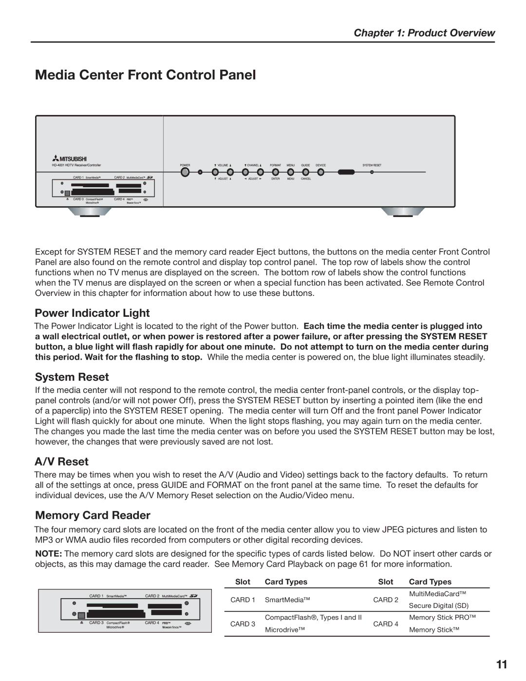
System Reset
A/V Reset
Chapter 1 Product Overview
Remote Control Overview
To send signals to the TV, point the remote control at the display
Installing the Batteries
Remote Control Operation
Figure 2. Operation Installing the Batteries
For Best Results from the Remote Control
3. AC Power Input
Display Rear Panel
Remove covers to access the signal and AC power inputs
A . MonitorLink RS-232C Control
1. IR Emitters and NetCommand
Media Center Rear Panel
A. MonitorLink RS-232C Control
B. MonitorLink A/V Output
12. AC Power Input
Media Center Rear Panel, continued
7. Audio Line Out
8. CableCARD Slot
Chapter
Connecting
Chapter 2 Connecting
Essential MonitorLink Connections
MonitorLink RS-232C Control and Digital A/V
#ONTROL EDIA #ENTER
Chapter 2 Connecting
AC Power Cords
$8BMM 0VUMFU
JTQMBZ .FEJB$FOUFS $8BMM 0VUMFU
Chapter 2 Connecting
External Devices and NetCommand Overview
FEJB$FOUFS
$IBSU
Cable Box
Wall Outlet Cable
Chapter 2 Connecting
$BCMF#PY
Separate UHF and VHF Antennas
Antenna with Twin Flat Leads
Chapter 2 Connecting
FEJB$FOUFS
About CableCARD Technology
Using a CableCARD
Chapter 2 Connecting
Antenna or Wall Outlet Cable to a VCR
Figure 8. Connecting a VCR to an Antenna or Wall Outlet Cable
4QMJUUFS
Chapter 2 Connecting
Cable Box to VCR
Figure 9. Connecting a VCR to a Cable Box
$BCMF#PY
Satellite Receiver or Other S-Video Devices
A/V Receiver or Stereo System
Chapter 2 Connecting
Figure 10. Connecting an A/V receiver
Chapter 2 Connecting
DVD Player or Other Component Video Device
Figure 12. Connecting a DVD Player with Component Video
See Appendix D for component video signal compatibility information
Chapter 2 Connecting
HDMI Output Device
Figure 13. Connecting the media center’s HDMI Device Input
FEJB$FOUFS
Chapter 2 Connecting
DVI Output Device
Figure 14. Connecting a DVI Device
FEJB$FOUFS VEJP
Chapter 2 Connecting
IR Emitters and NetCommand
Figure 15. Connecting IR Emitter NetCommand
7EFWJDF
Chapter 2 Connecting
IR Emitter Placement
Figure 16. IR Emitter Placement Recommendations
3TFOTPS
Chapter 2 Connecting
Compatible IEEE 1394 Device
1. Digital Video Signals
2. Digital Audio Signals
Chapter 2 Connecting
Connection Styles
4-Pin Style vs. 6-Pin Style Connectors
Direct Device-To-Device Style
analog audio and digital audio?
Helpful Hints
Chapter 2 Connecting
Chapter
NetCommand Setup and Editing
Chapter 3 NetCommand Setup and Editing
NetCommand Introduction
NetCommand makes your TV the heart of your Home Theater
Using NetCommand is completely optional
NetCommand Information Screen
NetCommand Initial Setup
Device Setup Screen
Chapter 3 NetCommand Setup and Editing
TV Guide On Screen System Setup
NetCommand Initial Setup, continued
Chapter 3 NetCommand Setup and Editing
Review Screen
Chapter 3 NetCommand Setup and Editing
Edit NetCommand Add an A/V Receiver
A/V Receiver Screen
A/V Receiver Inputs
A/V Receiver Input Learn Screen
Chapter 3 NetCommand Setup and Editing
A/V Receiver Learn Screen
Figure 8. A/V Receiver Input screen
Chapter 3 NetCommand Setup and Editing
Add an A/V Receiver, continued
Name Screen
Finish Screen
Edit NetCommand Screen
Edit NetCommand Add Devices
Chapter 3 NetCommand Setup and Editing
New Device Screen
Chapter 3 NetCommand Setup and Editing
Add Devices, continued
Device Learn Screen
Device Screen
Add Devices, continued
Chapter 3 NetCommand Setup and Editing
Device Advanced Learn Screen
Name Screen
Chapter 3 NetCommand Setup and Editing
Edit NetCommand Change Devices
Add Devices, continued
IR Code for Device Screen
Setup Reminder Screen
Edit NetCommand Delete Devices
Edit NetCommand Finish Screen
Chapter 3 NetCommand Setup and Editing
NetCommand Pre-Memorized Devices
Using the Remote Control with NetCommand
Chapter 3 NetCommand Setup and Editing
DEVICE
Cancel Button
NetCommand On-Screen Buttons
Chapter 3 NetCommand Setup and Editing
Back Button
Remote Control Buttons
3D Graphical Menu System
Chapter 3 NetCommand Setup and Editing
Menu Screens
Page
Chapter
IEEE 1394 Devices and NetCommand Controlled Recordings
Chapter 4 IEEE 1394 Devices and NetCommand Controlled Recordings
Using the “Learn” Feature to Control IEEE 1394 Devices
Chapter 4 IEEE 1394 Devices and NetCommand Controlled Recordings
Adding IEEE 1394 Devices Automatically
Name for 1394 Device Screen
New 1394 Device Screen
Chapter 4 IEEE 1394 Devices and NetCommand Controlled Recordings
Adding IEEE 1394 Devices Automatically, continued
IEEE 1394 Device Type Screen
Connection Screen
Chapter 4 IEEE 1394 Devices and NetCommand Controlled Recordings
Device Selection Menu
PIP Device Selection Menu
Device Section
Chapter 4 IEEE 1394 Devices and NetCommand Controlled Recordings
Using the DEVICE MENU Button to Display Menus
Device Menu
IR Controlled Devices
Chapter 4 IEEE 1394 Devices and NetCommand Controlled Recordings
Using the GUIDE Button to Display ChannelView and Menus
GUIDE and the Device Selection Menu
GUIDE and the Record To Menu
Setting up Recordings
NetCommand Controlled Recordings
Time-Delayed Recording
Chapter 4 IEEE 1394 Devices and NetCommand Controlled Recordings
Cancel Current Recordings
Peer-to-Peer Connections
Setting up a Peer-to-Peer Connection
Canceling a Peer-to-Peer Connection
Using the Remote Control with an A/V Disc
Using A/V Discs
Chapter 4 IEEE 1394 Devices and NetCommand Controlled Recordings
A/V Disc Track List Screen
Using Remote Control Buttons for Controlling Playback
MediaCommand and Memory Card Playback
Chapter 4 IEEE 1394 Devices and NetCommand Controlled Recordings
Inserting a Memory Card
Media Setup Menu
MediaCommand and Memory Card Playback, continued
Chapter 4 IEEE 1394 Devices and NetCommand Controlled Recordings
For JPEG Picture Slideshow Setup
Chapter 4 IEEE 1394 Devices and NetCommand Controlled Recordings
Direct VCR Recording from an Antenna or Cable Source
Copy-Protected Material
Restrictions for Traditional VCRs
Page
Main Menu Choices Setup Menu NetCommand Menu Antenna Menu Time Menu
TV Menu Operations
Captions Menu Customizing Digital Settings V-Chip Rating Guidelines
A/V Setting Descriptions
Setup Menu
Main Menu Choices
NetCommand Menu
Chapter 5 Using the TV Menu
Setup Menu
Language
Color Balance
NetCommand
NetCommand Menu
Default Digital Device
Chapter 5 Using the TV Menu
Antenna Menu
Memorize
Channel
SQV SuperQuickView Using The Menu Screen
Antenna Menu, continued
SQV SuperQuickView Using The Remote Control
Chapter 5 Using the TV Menu
Setting the Clock
Time Menu
Timer On/Off
Chapter 5 Using the TV Menu
Digital Settings
Captions Menu
Chapter 5 Using the TV Menu
CC1, CC2, CC3, or CC4. Standard closed captioning signals
Chapter 5 Using the TV Menu
Captions Menu, continued Customizing Digital Settings
Fonts
Size
V-Chip Signal Information
V-Chip Rating Guidelines
Chapter 5 Using the TV Menu
Content Categories
V-Chip Menu
V-Chip Lock Menu
Chapter 5 Using the TV Menu
V-Chip Lock Menu Overview
Chapter 5 Using the TV Menu
Setting V-Chip Options
The V-CHIP Button
Lock by Time
Settings
Audio/Video Menu
A/V Memory Reset
Chapter 5 Using the TV Menu
Analog and Digital Audio Setting
A/V Setting Descriptions Audio
Analog-Only Audio Settings
Digital-Only Audio Settings
Video Settings
A/V Setting Descriptions Video
Chapter 5 Using the TV Menu
NOTE For PC video settings, see Chapter
Page
Chapter
Connecting and Using a PC
82 Setting PC Resoluiton
Chapter 6 Connecting and Using a PC
Connecting a PC to the Display
Figure 1. Connecting a PC to the Display
JTQMBZ3FBS1BOFM
Chapter 6 Connecting and Using a PC
Setting PC Resoluiton
Displayed Format
PC Display Formats
Chapter 6 Connecting and Using a PC
Supported PC Timings
PC Video Settings
Chapter 6 Connecting and Using a PC
Horiz Res Horizontal Resolution
Page
Troubleshooting Using the System Reset Button Using the Reset Menu
Troubleshooting and Support
Chapter
Support
Chapter 7 Troubleshooting and Support
Troubleshooting
Problem
Possible Solution
Problem
Chapter 7 Troubleshooting and Support
Possible Solution
V-Chip is not working
Problem
Chapter 7 Troubleshooting and Support
Possible Solution
Devices are grayed out in the Device Selection
Problem
Chapter 7 Troubleshooting and Support
Possible Solution
All IEEE 1394 devices disappear
Using the Reset Menu
Using the System Reset Button
Support
Chapter 7 Troubleshooting and Support
Appendices
Signal Type
Appendix A Specifications
Signal Type
Signal Type
RCA Pin Plug, Signal Type, Dolby Digital
Appendix A Specifications, continued
Dimensions
Weight
Sleep Timer
Appendix B On-Screen Information Displays
Sleep Timer
3 DVHS Monday 1100 AM Sleep Timer
Appendix C Bypassing the V-Chip Lock
Been
C u t A l o n g
i s L
This page intentionally blank
NetCommand IEEE 1394 System Compatibility
Appendix D Input Connection Compatibility
Component-1 and Component 2 Inputs
VGA Input on rear panel of display
Input Signal
Appendix E Scan Rates for Input/Output Sources
Input Signal
Scan Rates for VCR or Non-HD Monitor OUTPUT source
Automatic POP Switching
Appendix F Using PIP and POP
Changing PIP/POP Device
Changing PIP/Side-by-Side Channels
TV Signal Definitions
Appendix G TV Display and DVD Formats
TV Display Formats
TV Format Definitions
ORIGINAL SIGNAL
Appendix G TV Display and DVD Formats, continued
ORIGINAL SIGNAL
Non-anamorphic or SD
Programming the Remote to Control NetCommand A/V Products
Appendix H Remote Control Programming Codes
A/V Receivers
Cable Boxes
Cable Boxes, continued
Appendix H Remote Control Programming Codes, continued
DVD Players
Satellite ReceiversSAT/DTV
Cable Boxes and Satellite Receivers
Appendix H Remote Control Programming Codes, continued
A/V Receivers
Mitsubishi A/V Receivers
When Net Command Compatible Traditional Device is Viewed or Played
Appendix I Device Control with NetCommand
POWER
CANCEL
When an IEEE 1394 Device is Viewed or Played
Appendix I Device Control with Net Command, continued
POWER
CANCEL
CABLE
Appendix J NetCommand Specialized Device Keys
LEARNING SCREEN
FUNCTION
Changing the Color Temperature
Appendix K Changing the Color Temperature of the Display
Be sure to follow the procedure below exactly as stated, step by step
Color Temperature Options
Cleaning
Appendix L Cleaning
General Cleaning Warnings
Top and Sides of the Display and Media Center
Trademark and License Information
END-USER LICENSE AGREEMENT FOR EMBEDDED SOFTWARE
MITSUBISHI LT-3280/LT-3780 LCD FLAT PANEL HDTV SOFTWARE
1. TO OBTAIN WARRANTY SERVICE
MITSUBISHI LT-3280/LT-3780 LCD FLAT PANEL HDTV LIMITED WARRANTY
2. THIS LIMITED WARRANTY DOES NOT COVER
MITSUBISHI DIGITAL ELECTRONICS AMERICA, INC. 9351 Jeronimo Road
Index
Index
Index
Page
For questions, contact Consumer Relations at Telephone
Email MDEAservice@mdea.com
2005 Mitsubishi Digital Electronics America, Inc
Written and Printed in U.S.A