Page
Page
136458±001, Rev B
Copyright 1995, PRINTRONIX, INC
Trademark Acknowledgments
Page
Table of Contents
Commands
PTXSetup
Page
Bar Codes
Multinational Character Sets
Form Examples and Exercises
Error Codes
Introduction
Chapter Contents
About this Manual
How to Locate Information
Features
Introduction
How the IGP/PGL Operates
±1. IPG/PGL Modes
Modes of Operation
Normal Mode
Command Mnemonic Description
±1. Normal Mode Commands
Uppercase
Quiet Mode
Create Form Mode
±2. Create Form Mode Commands
Execute Form Mode
Create Logo Mode
LPI Iset Normal Paper Reset Sfon Sfoff
±3. Execute Form Mode Commands
AutoEject
Configuration Mode
Ext Execute Copy
Option Parameter Comments Value
Value Select Font
Option Parameter Comments
BEL
±5. Ascii Conversion Table
Incremental Data
Alphanumeric Data
±18 Introduction
Configuration
Configuring the IGP/PGL with the Control Panel
IGP/PGL Emulation Submenu
±1. The Configuration Menu
Define LF Code Line Feed
Define CR Code Carriage Return
Autowrap
Select Sfcc
Auto Eject
Select Font
Select LPI
S. Ascii
Power On IGP/PGL
Skip Command Prefix
Auto Uppercase
Extended Execute Copy
IGP100 Compatibility
UPC Descenders
Host Form Length
Configuration
PTXSetup
Ptxend
PTXSetup Command Description
Ptxsetup
End command for the PTXSETUP. When
Diskio
PTXSetup Command Parameters and Values
Fontend
DELªfilenameº
Ptxsetup ENGINE±LENGTH11000WIDTH8500 Ptxend
PTXSetup Command Example
Commands
Page
Inline Commands
IGP/PGL Command Standards
Special Function Control Character Sfcc
Semicolon
Printable Character
Line Terminator
Form Name
Command Parameters
Spaces
Prompt
Comments in Command Lines
Numeric Values
Storing Data
Character Position.Dot Position CP.DP Format
Uncompressed and Packed Bits Compression
±1. CP.DP Format Example
Fixed Data
Data Fields for Alphanumeric and Incremental Data
Overlay Data
Dynamic Data
Incremental Data Fields
Dark Printing
Thermal Printers
Line-Matrix Printers
±2. Dark Printing
Purpose
Alphanumerics
Mode
Format
DIR
Point
Stop
CCW454800*E INV454800*E
±3. Alphanumeric Example
Alphanumerics, Incremental Fields
Using Incremental Alphanumeric Data
Stepmask Start Data
±1. Increment Alphanumeric
±20 Commands
Commands ±21
Alpha
Alphanumerics, Incremental Fixed Data Fields
RPTn RSTn Dstartdatad
Idir
Startdata
RSTn
Vdupoff END
~CREATETEST288
~EXECUTETEST
~NORMAL
IAFnL
Alphanumerics, Incremental Dynamic Data Fields
Cn IAFnL DIR UC SR SC VE HE Stop
±26 Commands
Commands ±27
Where
VDUP36 Repeats alpha string
BOX
Boxes
LT SR SC ER EC
Stop BOX
Box command parameters
Stop indicates the end of the Box command enter
Defines the ending column of the box. Enter a value
Ranging from column 2 through the last column
±4. Box Example
~DENSITY15
Compressed Print Density
Density
Config
Configuration
±2. Config Command Parameters
Normal
~CONFIG Reset END
~CONFIG Auto WRAP1 Auto EJECT0 LPI6 END
Corner
Corners
LT SR SC ER EC VL HL
Stop Corner
Based on the Scale command page 4±88, or use
On the Scale command page 4±88, or use the CP.DP
Stop indicates the end of the Corner command
Another set of Corner command parameters
±5. Corner Example
Formname
Create
Format ccCREATE /formname FL Disk
Maximum length of the form. Form length cannot
Optional forms length parameter to specify
Exceed the physical length of the page. Refer to
Appendix C. Specify the form length in one of three
Delete Form
Delete Form
Disk
~DELETE FORMPAY#DISK
Delete Logo
Delete Logo
Logoname
Example
Directory
Directory
Hdupoff
Duplication, Horizontal
Dup#
Offset#
Vert
Vdupoff
Duplication, Vertical
Horz
Format END
End
How to Use the Execute Command
Execute Form Mode
Print Formats in the Execute Form Mode
Execute Form General Format
Data, or Evfu data are used in the Execute command
When the last page prints, the IGP/PGL returns to
Optional form count parameter specifies
Number of copies of the form to print. Enter
Form Feed Character
Ascii text
Execute Form Dynamic Alphanumeric Data
CcAFn Dascii textD
Data field
Execute Form Dynamic Bar Code Data
Format ccBFn Ddata fieldD
CcEXECUTE formname page n FC ICNTn IRSTn
Execute Form Incremental Dynamic Data
IAF
Supplying Dynamic Data for Incremental Fields
IBF
Idir
Startdata
Execute Form Overlay Data
Expand
Expanded Print
NORMAL, Execute
Format ccFONT Face # Bold # Slant # Symset # Point #
Font
Font
Face #
Slant #
Bold #
Symset #
Point #
Page
LFORM6
Form Length
LFORM8
LFORM648
Igoff
Ignore Sequence
Igon
LPI
Line Spacing
Stop Horz
Lines, Horizontal
LT R SC EC
±68 Commands
Stop Vert
Lines, Vertical
LT C SR ER
±70 Commands
Listen
Listen
Logo
Logo Call
SR SC logoname
Stop Logo
Stop
CcLOGO logoname VL HL Disk
Logo Mode, Create
Row# dot Dot1±dot2 dot
Row#
END
Terminates the Create Logo mode enter END
~LOGOTAPEHOLD3640
Normal Mode
SR SC
Number
Paper
Speed
Rotate #
Ribsave #
Tear #
PCX
PCX Logo
PCX raster data
Rasterend
Page
Print File
~PRINTSETUP.PTX
Print
Filename
Quiet
Quiet
Reset
Reset
Reverse
Reverse Print
Dark SR SC ER EC
Stop Reverse
Stop indicates the end of the Reverse command
Dot column is specified based on the Scale command
Command. If not entered, the IGP/PGL will expect
Another set of Reverse Print command parameters
Scale
Value from 1 to the target DPI. The default is 6 lpi
DOT
Char
Page
Select Format
Command Paper Movement Function
Sfon
Sfoff
Setup
Setup
Setupend
Host Data
Tiff raster data
Tiff Logo
Tiff
Page
±94 Commands
Bar Codes
±1. Available Bar Codes
Overview
Code Code 128 ± Subset B Subset C Codabar Code UCC±
Interleaved 2/5
Postnet UPC±A UPC±E UPC±E0
Postnet
UPC±E and UPC±E0
User±Defined Variable Bar Code Ratios RDratio
Format Size Avg. X Dim Ratio
±2. T3306 & T3308 Binary Bar Code Sizes
Bar Codes
±3. T3306 & T3308 Binary Bar Code Sizes CW & CCW Drawing
±3. T3306 & T3308 Binary Bar Code Sizes
20 mil Landscape
±5. T3306 & T3308 4-Element Bar Code Sizes CW & CCW Drawing
±5. T3306 & T3308 4-Element Bar Code Sizes
Bar Codes ±13
±6. T3204 & T3304 Binary Bar Code Sizes
16.7 mil 671 Portrait
±7. T3204 & T3304 Binary Bar Code Sizes
±7. T3204 & T3304 Binary Bar Code Sizes CW & CCW Drawing
Mil 331 26.7 mil
±9. T3204 & T3304 4-Element Bar Code Sizes CW & CCW Drawing
±9. T3204 & T3304 4-Element Bar Code Sizes
~CREATETEST
Variable Ratio Sample
Scalechar Alpha
Barcode
±20
±1. Code 39 Structure
Code
Start/Stop Codes
Quiet Zone
Data Field
Readable Data
C3/9 CD Vscan MAG Hn.m BFnL Dark SR SC Ddata fieldD
Code 39 Command Format
MAG
Hn.m
Dark
BFnL
Font
LOC
±10. Code 39 Character Set
Code 39 Example
~CREATEC39
Sample C3/9
±2. Sample Code 39 Bar Codes
±3. Code 93 Structure
Code 93 Data Field
Vscan
Code 93 Command Format
CODE93
To use this field, perform the following steps
Same character must be used at both ends
±11. Code 93 Character Set
Scalechar Barcode
Code 93 Example
±4. Codabar Structure
Codabar
Quiet Zone
Codabar CD
Codabar Command Format
Codabar CD Vscan MAG Hn.m BFnL Dark SR Ddata fieldD
±38
Bar Codes ±39
±12. Codabar Character Set
~EXECUTETEST ~NORMAL
Codabar Example
CODABARVSCANX1H7520
±5. Code 128 Structure
Code 128B and Code 128C
Code 128C Data Field
Code 128B Data Field
C128C
Code 128 Command Format
Dark
Sfcc
±13. Code 128B Character Set
±14. Code 128C Character Set
~CREATE128B
Code 128B Example
Sample Code 128B
~EXECUTE128B1
~EXECUTE128C1
Code 128C Example
~CREATE128C
±8. Code UCC±128 Structure
Code UCC ±128
Quiet Zone
UCC±128
Code UCC±128 Command Format
Dark
Not print with the data
Must be used at both ends of the data field, but it will
~EXECUTEUCC±1281
Code UCC±128 Example
~CREATEUCC±128
EAN
Start/Center/Stop Codes
SCB
EAN 8 Command Format
EAN8 +n Vscan SCB MAG Hn.m BFn Dark SR Ddata fieldD
Inches
Form. Character row or dot row is specified based on
Scale command page 4±88, or use the CP.DP
Ranging from row 1 to one less than the length
Trailing lower portions of the EAN bar code
Readable data field. The default value, N, selects
Font. Enter S to suppress printing the data field
~EXECUTEEAN81
EAN 8 Example
~CREATEEAN8
±12. EAN 13 Structure
EAN
Number System Character
EAN13 +n Vscan SCB MAG Hn.m BFn Dark SR Ddata fieldD
EAN 13 Command Format
±10 for more information
Optional parameter to produce darker looking bar
Codes. Enter DARK. Refer to ªDark Printingº on
Or upper side on vertically oriented symbols
Vertically oriented symbols can be encoded in either
Left side of the data field or lower side on
Number system character. a bar code character is not
±15. Left Side Data Field Format
~EXECUTEEAN131
EAN 13 Example
~CREATEEAN13
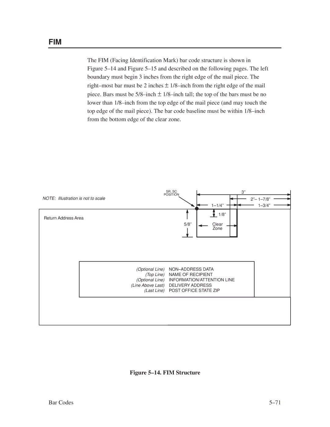
FIM
±15. FIM Structure Vscan
Start/Stop Code
Clear Zone
FIM Vscan Hn.m BFn Dark SR SC Ddata fieldD
FIM Command Format
Row or dot row is specified based on the Scale
~EXECUTEFIMB1
FIM Example
~CREATEFIMB
~EXECUTEFIMC1
~CREATEFIMC
POSTNETDARK33.315
±18. I±2/5 Structure
Interleaved 2/5 I±2/5, German I±2/5
Quiet Zone
I25GERMAN Vscan MAG Hn.m BFnL Dark SR SC D data field D
±2/5 Command Format
Bar Codes ±81
Character used within the data
Defines the starting row for the bar code. Enter a value
Same character must be used at both ends
Data field, but it will not print with the data
Printable data field above bar code
±2/5 Example
To compensate for printing the 0.1±inch high data,
Height of the bar code body is reduced 0.1±inch
±19. Sample I±2/5 Bar Codes
MSI
Quiet Zone
MSI n Vscan MAG Hn.m BFnL Dark SR SC Ddata fieldD
MSI Command Format
Default value is 0.9±inch. .m is an additional
Printable data field above the bar code. To compensate
Not print
For printing the 0.1±inch high data, the height
Bar code body is reduced 0.1±inch
Font
~CREATEMSI
MSI Example
MSIADARK3227
MSIBVSCANX2H12DARK3254
±92
Security Level
YDn
XDn
This parameter is used
Character other than a slash /, the SFCC, or a
Execute the form
Postnet
±25. Postnet Structure Vscan
Clear Zone
Postnet
Postnet Command Format
Defines the starting row for the bar code. Enter a value
POSTNETDARK1040
~CREATEPOSTNET
POSTNETVSCANDARK1020
~EXECUTEPOSTNET1
UPC±A
Quiet Zone
UPC±A +n Vscan SCB MAG Hn.m BFn Dark SR Ddata fieldD
UPC±A Command Format
Bar Codes ±107
Data. Use the same character at both ends
Character used within the data. It will not print with
Command format, the data field is printed
Readable data field. The default font type for UPC±A
Code body is reduced 0.1±inch
Automatically in OCR±B. Entering X will also
~EXECUTEUPCA1
UPC±A Example
~CREATEUPCA
±29. UPC±E and UPC±E0 Structure
UPC±E and UPC±E0
Quiet Zone
UPC±E or UPC±E0
UPC±E and UPC±E0 Command Format
Type
±114
OCR±B
Command format, the data field will print
Readable data field. The default font type for UPC±E
±16. Eleven Digit Compression
±17. Six±Digit Zero Expansion
~EXECUTEUPCE1
UPC±E and UPC±E0 Example
~CREATEUPCE
Incremental Bar Code Fields
±18. Incremental Bar Code Data
Incrementing Bar Code Data
Bar Codes
Bar Codes ±123
Idir Stepmask RPTn RSTn Dstartdatad
Incremental Bar Code Fixed Data Fields
Type Vscan MAG Hn I Dark SR SC
65,535 to specify the repeat count
VDUP36
IBFnL
Incremental Bar Code Dynamic Data Fields
Barcode Stop
Duplicating Incremental Bar Code Fields
C3/9H7IBF1665
±130
Form Examples and Exercises
Form Examples
Form Examples and Exercises
±1. Basic Create Form Example
~SETUP Config TOP/BOTTOM Margin 1 Left Margin END
Example Using the Setup Command
~SETUPEND
Example Dynamic Data
~EXECUTESAMPLE1 ~NORMAL
~CREATESAMPLE390
±2. Sample Form
Bar Code Fields
First bar code command
Begin alpha command for dynamic data
~EXECUTESAMPLE
~AF2*1234 Anywhere ST
~FF
~AF1*ABC Corporation
Page
±3. Dynamic Data Example
Example Auto Increment Fields
Form Examples and Exercises ±15
±16 Form Examples and Exercises
±4. Auto Increment Fields Example
±5. Auto Increment Fields Example
Form Exercise
Stop END
PRACTC.FRM
EnterFormat
±6. Box and Corner Example
System Format
±7. Box/Corner Example with Horizontal and Vertical Lines
RECnAFnLDIRUCDARKSRSCVEHEDTextD
Enter
Stop END ~EXECUTE Practice ~NORMAL
~CREATEPRACTICE
±8. Practice Form Example
Barcode C3/9H8BF15DARK35.739
Alpha previously input
C3/9H8BF15DARK35.739
±9. Completed Practice Form Example
Logo Exercise
±10. Sample Logo
SRSClogoname Disk
HNDLGO.FOM
~CREATELEFTHAND
EnterFormat
±36 Form Examples and Exercises
Layout Considerations
Form Design
Planning the Form Layout
Form Examples and Exercises ±39
±11. Sample Form Design
Form Examples and Exercises ±41
Vertvert
Boxbox
Stop Vdupoff
Ltrscec
Logo 1218HANDCRFT
Dark Srsc
Ddatafield D
EnterFormat
±13. Completed Sample Form
Print DIRECT.FOM
Directory Example
DIRECT.FOM
DELETE.FRM
Delete Example
~DELETE Formpractice
~DELETE Formhcboats ~DELETE Logohandcrft
Solving Program Errors
±50 Form Examples and Exercises
Multinational Character Sets
±1. Multinational Character Sets and Set Values
About the Multinational Character Set
Character Sets Available
Making Character Substitutions
Character Addresses
Page
±2. Substitution Set Hex Values
OCR Character Sets
Data Bit
Accessing Characters and Character Sets
Power±Up Character Set Selection
Uset
User±Defined Set Command Uset
Cafa
~USET1
±3. USET±ISET Relationship
Iset
Character Set Selection Command Iset
Multinational Character Sets
±12 Multinational Character Sets
Multinational Character Sets ±13
±14 Multinational Character Sets
Error Codes
CCCREATE/FORM Name
Purpose of Error Codes
Horizontal Line Errors
Vertical Line Errors
Box Errors
Corner Errors
Corner starting row SR ending row ER
Corner starting column SC ending column EC
Alpha leading and trailing delimiters mismatched
Alpha Errors
Alpha starting row SR out of bounds
Alpha starting column SC out of bounds
Alpha X expansion HE and Y expansion VE must be zero
Logo Errors
Logo call starting row SR out of bounds
Insufficient memory for another Logo call
Logo call starting column SC out of bounds
Color or Gray scale not supported with Logos
Create Errors
Insufficient memory to store the Setup program
Create Stop command missing
Create page starting column page SC out of bounds
Insufficient memory to store the form
Execute Errors
Insufficient memory to Execute the form
Execute format or delimiter error
Miscellaneous Errors
Expand parameters out of bounds or format error
Bar Code Errors
Barcode symbols exceeds the form width
Barcode symbols exceeds the form length
Barcode data field too short or too long
Barcode variable ratio 0 or not ascending
Dynamic Barcode field longer than previously defined
Sfcc decimal input error ± must be 01 to
LFORMx form length parameter n error
Reverse Print Errors
Form length physical page length
FORM/LOGO name is not a legal file name
Incremental Fields Errors
Multinational Character Set Errors
Font Errors
Standard Ascii Character Set
Ascii Character Set
Grid Programs and Samples
Grid Programs and Samples
Page
Grid Programs and Samples
Paper Selection and Maximum Values
Boundaries
Boundaries
Length
Figure C±1. Top/Bottom Margin Example
Setting Top/Bottom Margins
Setting Left Margins
Figure C±2. Left Margin Example ± No Setting
Figure C±4. Left Margin ±20 Setting Example
Boundaries
Standard and Optional Typefaces
Typefaces
Antique Olive
Albertus
ITC Avant Garde Gothic
Monotype Baskerville
CG Bodoni
ITC Benguiat
ITC Bookman
Decorative
90326 90133 90349 90508
ITC Century
Caslon
CG Century Schoolbook
ITC Cheltenham Book
ITC Clearface
Clarendon
Courier
Futura
Garamond Antiqua
ITC Galliard
Garth Graphic
Gill Sans
Hiroshige
CG Goudy Old Style
ITC Korinna
Letter Gothic
Microstyle
ITC Lubalin Graph
CG Melliza
CG Palacio
CG Omega
Shannon
ITC Souvenir
ITC Tiepolo
Stymie
ITC Tiffany
CG Times
CG Triumvirate
CG Trade
CG Triumvirate Condensed
CG Trump Mediaeval
Univers Condensed
Univers
ITC Zapf Chancery
ITC Zapf Dingbats
Chart Printing Package 141783±008 Seven Fonts
Chart Printing Package 141783±008
Desktop Printing Package 141783±010 Eight Fonts
Desktop Printing Package 141783±010
Label Printing Package #1 141783±006 Eight Fonts
Label Printing Package #1 141783±006
Label Printing Package #2 141783±007 Eight Fonts
Label Printing Package #2 141783±007
Office Printing Package 141783±009 Eight Fonts
Office Printing Package 141783±009
CG Century Schoolbook Family 141783±005 Four Fonts
CG Times Family 141783±004 Four Fonts
CG Triumverate Family 141783±003 Four Fonts
Garamond Family 141783±011 Four Fonts
Gill Sans Family 141783±002 Five Fonts
Gill Sans Family 141783±002
Univers Family 141783±001 Four Fonts
POSTNET, 5±3
Index
Page
POSTNET, 5±97
Page
Page
Page
Page
Page
Page
Index±10
Page
6662