RGB Source to Input 3
Which signal to Input 3
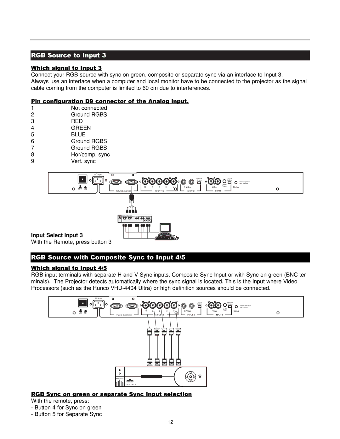
Connect your RGB source with sync on green, composite or separate sync via an interface to Input 3.
Always use an interface when a computer and local monitor have to be connected to the projector as the signal cable coming from the computer is limited to 60 cm due to interferences.
Pin configuration D9 connector of the Analog input.
1 | Not connected |
2 | Ground RGBS |
3 | RED |
4 | GREEN |
5 | BLUE |
6 | Ground RGBS |
7 | Ground RGBS |
8 | Hor/comp. sync |
9 | Vert. sync |
AC Input
OFF/ON 75 Ohm
|
|
|
|
|
|
|
|
|
| R | G | B | H | V |
| ||||
OFF ON |
| Future Expansion |
|
|
|
|
| INPUT 4/5 |
|
|
|
|
| INPUT 2 | |||||
|
|
|
|
|
|
|
|
|
|
|
|
|
|
|
|
| |||
|
|
|
|
|
|
|
|
|
|
|
|
|
|
| |||||
|
| OFF/ON |
|
| 75 Ohm |
|
| Green: Operation |
| 12 Volt | Red: Standby |
|
| |
Video | Trigger | Status |
|
INPUT 1
ON | ANALOG INTERF. 120MHz |
OFF![]()
R G
INPUT
B HV
INP INP
Input Select Input 3
With the Remote, press button 3
RGB Source with Composite Sync to Input 4/5
Which signal to Input 4/5
RGB input terminals with separate H and V Sync inputs, Composite Sync Input or with Sync on green (BNC ter- minals). The Projector detects automatically where the sync signal is located. This is the Input where Video Processors (such as the Runco
AC Input
OFF ON
Future Expansion
R G B H V
INPUT 4/5
OFF/ON 75 Ohm
INPUT 2
|
| OFF/ON |
|
| 75 Ohm |
|
| Green: Operation |
| 12 Volt | Red: Standby |
|
| |
Video | Trigger | Status |
|
INPUT 1
Menu |
4404 ULTRA |
RUNCO |
M U L T I F I L M |
RGB Sync on green or separate Sync Input selection With the remote, press:
-Button 4 for Sync on green
-Button 5 for Separate Sync
12
