I/O CONNECTION
Input Connection
183
%003
Mon 12 / 12 / 2009
10 : 30 : 20
1 2 3 F1 F2 F3
4 5 6 F4 F5 F6
7 8 9 F7 F8 F9
ESC 0 ENT F10 F11 F12
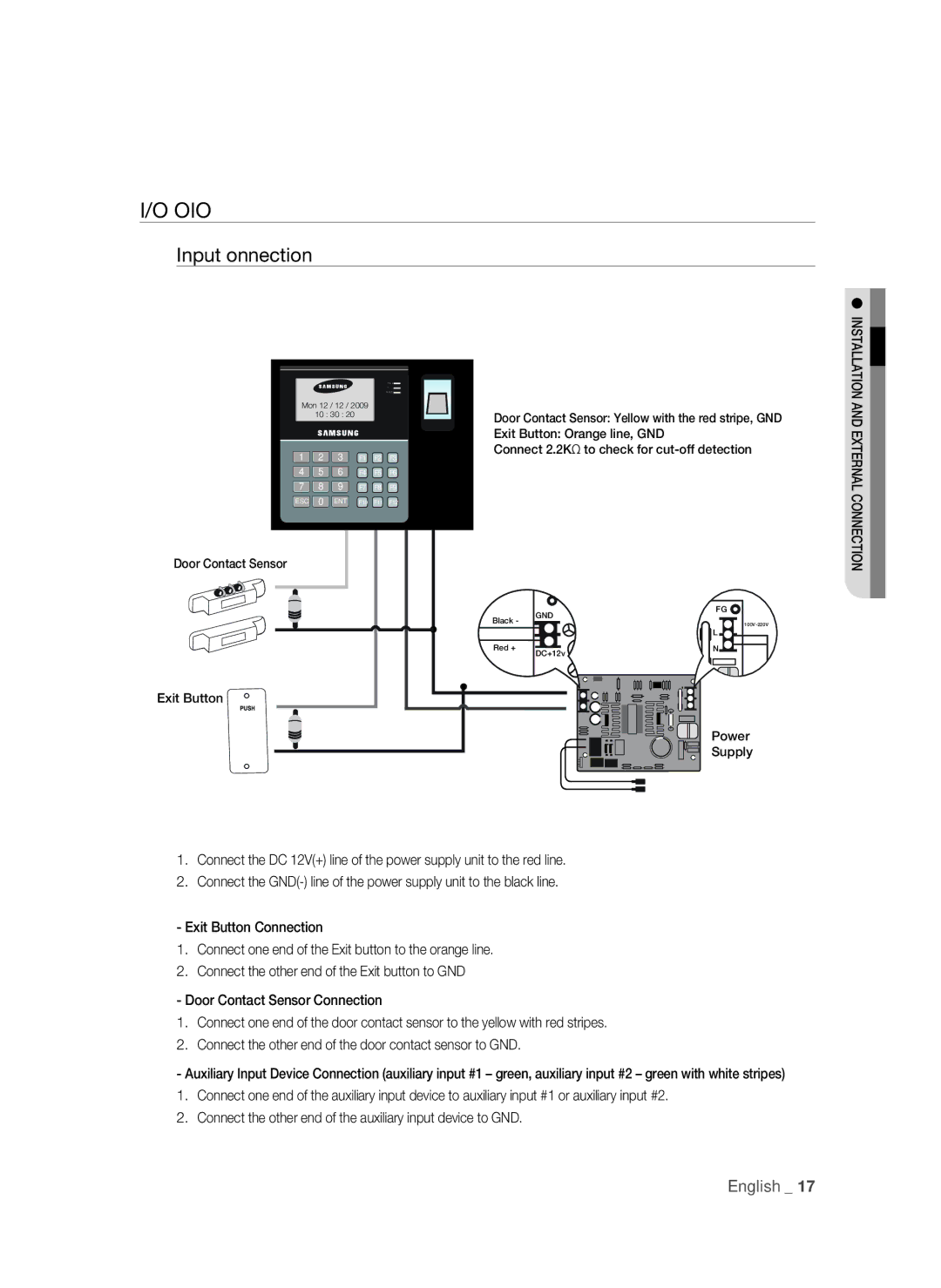
Door Contact Sensor
Exit Button
Door Contact Sensor: Yellow with the red stripe, GND
Exit Button: Orange line, GND
Connect 2.2K to check for
| GND | FG |
Black - |
| |
| ||
|
| L |
Red + | DC+12v | N |
|
|
Power
Supply
INSTALLATION AND EXTERNAL CONNECTION
1.Connect the DC 12V(+) line of the power supply unit to the red line.
2.Connect the
- Exit Button Connection
1.Connect one end of the Exit button to the orange line.
2.Connect the other end of the Exit button to GND
- Door Contact Sensor Connection
1.Connect one end of the door contact sensor to the yellow with red stripes.
2.Connect the other end of the door contact sensor to GND.
- Auxiliary Input Device Connection (auxiliary input #1 – green, auxiliary input #2 – green with white stripes)
1.Connect one end of the auxiliary input device to auxiliary input #1 or auxiliary input #2.
2.Connect the other end of the auxiliary input device to GND.
English _ 17