INPUT TEST
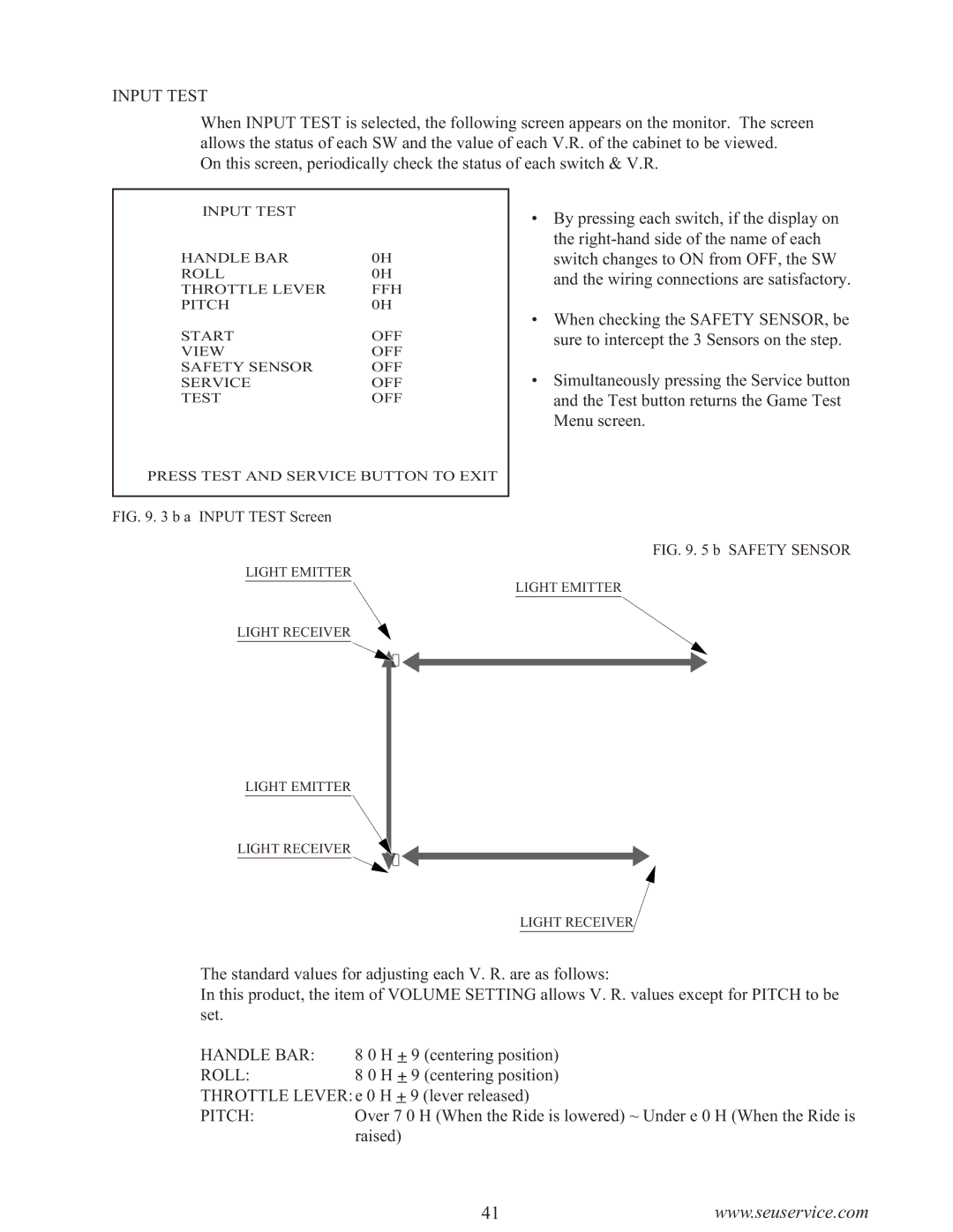
When INPUT TEST is selected, the following screen appears on the monitor. The screen allows the status of each SW and the value of each V.R. of the cabinet to be viewed.
On this screen, periodically check the status of each switch & V.R.
INPUT TEST |
|
HANDLE BAR | 0H |
ROLL | 0H |
THROTTLE LEVER | FFH |
PITCH | 0H |
START | OFF |
VIEW | OFF |
SAFETY SENSOR | OFF |
SERVICE | OFF |
TEST | OFF |
PRESS TEST AND SERVICE BUTTON TO EXIT
•By pressing each switch, if the display on the
•When checking the SAFETY SENSOR, be sure to intercept the 3 Sensors on the step.
•Simultaneously pressing the Service button and the Test button returns the Game Test Menu screen.
FIG. 9. 3 b a INPUT TEST Screen
FIG. 9. 5 b SAFETY SENSOR
LIGHT EMITTER
LIGHT EMITTER
LIGHT RECEIVER
LIGHT EMITTER
LIGHT RECEIVER
LIGHT RECEIVER
The standard values for adjusting each V. R. are as follows:
In this product, the item of VOLUME SETTING allows V. R. values except for PITCH to be set.
HANDLE BAR: | 8 0 H + 9 (centering position) |
ROLL: | 8 0 H + 9 (centering position) |
THROTTLE LEVER:e 0 H + 9 (lever released) | |
PITCH: | Over 7 0 H (When the Ride is lowered) ~ Under e 0 H (When the Ride is |
| raised) |
41www.seuservice.com
