3Loosen the 2 screws that secure the V.R. Bracket to move the V.R. Bracket.
4Move the V. R. Bracket to disengage the Adjust Gear mesh and move the V.R. shaft so that the cut part of the shaft may turn to the opposite side of the Adjuster Gear as shown.
5Engage the gear and tighten the 2 screws.
6Carefully turn the Handle Shaft to the left/right and ensure that the V.R. value variations are within the range of the Volume.
7After finishing adjustments, be sure to perform the Handlebars Volume Setting in the Test Mode (see
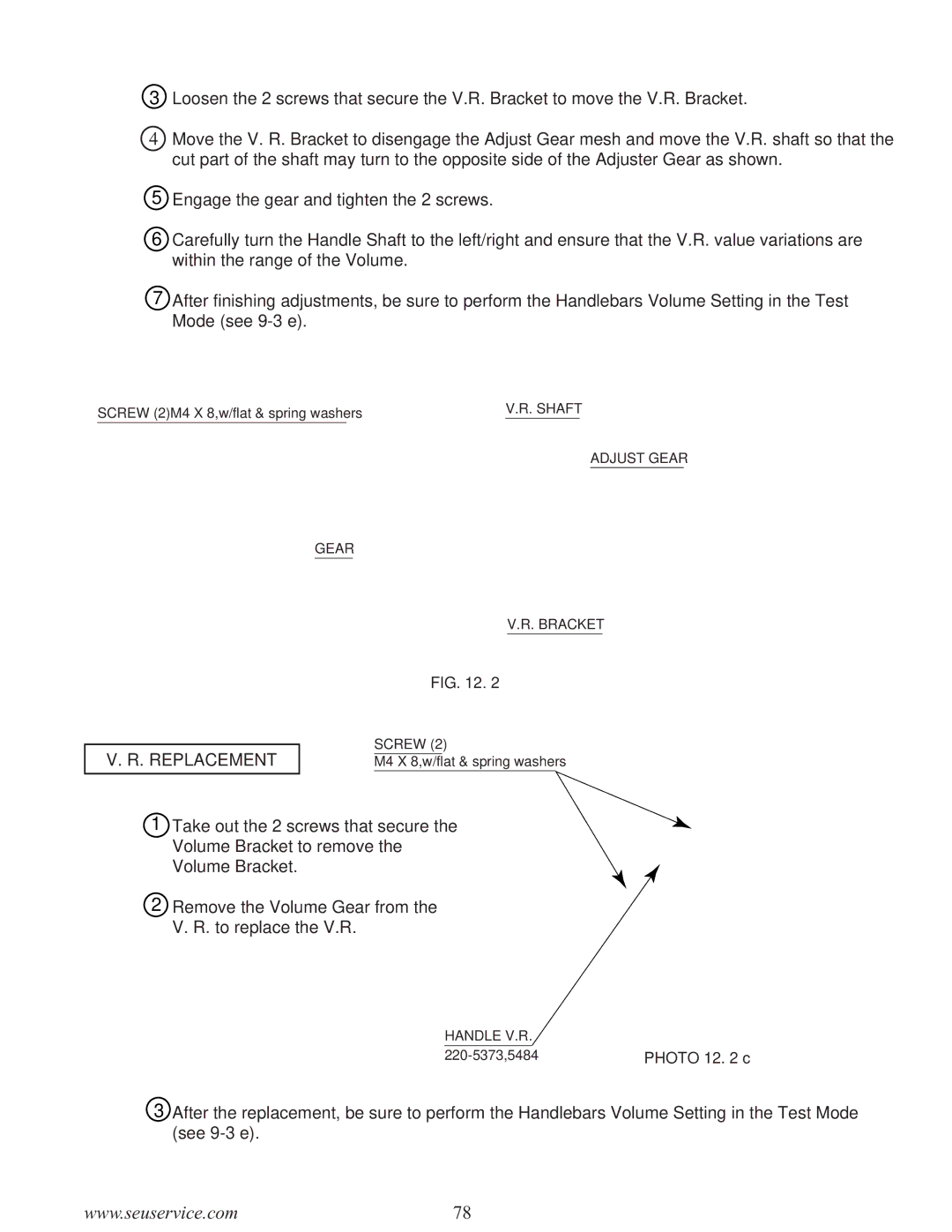
SCREW (2)M4 X 8,w/flat & spring washers |
| V.R. SHAFT |
|
|
|
ADJUST GEAR
GEAR
V.R. BRACKET
FIG. 12. 2
V. R. REPLACEMENT
SCREW (2)
M4 X 8,w/flat & spring washers
1 Take out the 2 screws that secure the Volume Bracket to remove the Volume Bracket.
2Remove the Volume Gear from the V. R. to replace the V.R.
HANDLE V.R. |
|
PHOTO 12. 2 c |
3After the replacement, be sure to perform the Handlebars Volume Setting in the Test Mode (see
www.seuservice.com | 78 |