2. PHYSICAL DESCRIPTION
The SIGMA SYSTEMS Model C4 Controller fits into an area 3.5" x 5.5" x 9.5" long. Connection to the chamber or platform is made through an umbilical cable with a 12 pin connector that is standard for all SIGMA chambers and thermal platforms. Controllers destined for use with SIGMA thermal platforms have an additional 6 pin connector used for the sensor probe circuits. All C4 controllers have a 3 pin “pigtail” connector at the back of the controller for control of refrigeration via solid state relay. This feature was optional on
2.1 Front Panel
The front panel consists of four major parts: the LED digit display, the LED indicators, the mode switch and the keypad. The numbers in circles on the front panel guide the user through the steps for changing the temperature setting in the LOCAL (manual) mode of operation. See Section 5.
2.1.1 Digital LED Display
The Digital LED Display is a 7 digit display arranged in the following configuration:
The display is used for showing probe temperatures, setpoints, program steps,
2.1.2 LED Indicators
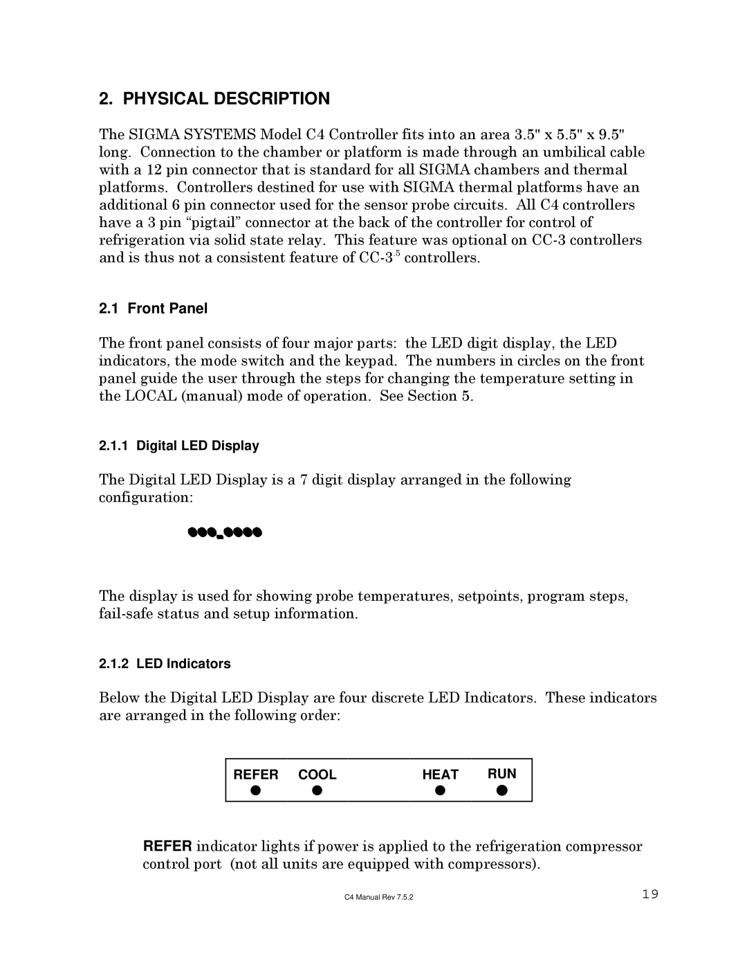
Below the Digital LED Display are four discrete LED Indicators. These indicators are arranged in the following order:
REFER | COOL | HEAT | RUN |
| | | |
|
|
|
|
REFER indicator lights if power is applied to the refrigeration compressor control port (not all units are equipped with compressors).
C4 Manual Rev 7.5.2 | 19 |
