9.5 Installation and Use of TTL Outputs and Input
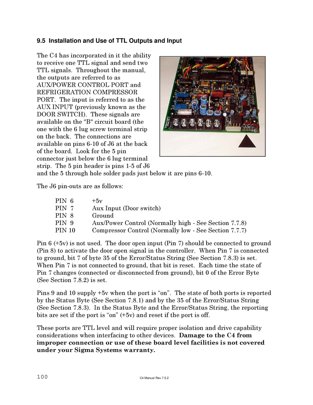
The C4 has incorporated in it the ability to receive one TTL signal and send two TTL signals. Throughout the manual, the outputs are referred to as AUX/POWER CONTROL PORT and
REFRIGERATION COMPRESSOR PORT. The input is referred to as the AUX INPUT (previously known as the DOOR SWITCH). These signals are available on the "B" circuit board (the one with the 6 lug screw terminal strip on the back. The connections are available on pins
and the 5 through hole solder pads just below it are pins
The J6
PIN 6 | +5v |
PIN 7 | Aux Input (Door switch) |
PIN 8 | Ground |
PIN 9 | Aux/Power Control (Normally high - See Section 7.7.8) |
PIN 10 | Compressor Control (Normally low - See Section 7.7.7) |
Pin 6 (+5v) is not used. The door open input (Pin 7) should be connected to ground (Pin 8) to activate the door open signal in the controller. When Pin 7 is connected to ground, bit 7 of byte 35 of the Error/Status String (See Section 7.8.3) is set.
When Pin 7 is not connected to ground, that bit is reset. Each time the state of Pin 7 changes (connected or disconnected from ground), bit 0 of the Error Byte (See Section 7.8.2) is set.
Pins 9 and 10 supply +5v when the port is “on”. The state of both ports is reported by the Status Byte (See Section 7.8.1) and by the 35 of the Error/Status String (See Section 7.8.3). In the Status Byte and the Error/Status String, the reporting bits are set if the port is “on” (+5v) and reset if the port is off.
These ports are TTL level and will require proper isolation and drive capability considerations when interfacing to other devices. Damage to the C4 from improper connection or use of these board level facilities is not covered under your Sigma Systems warranty.
100 | C4 Manual Rev 7.5.2 |