Some errors, especially those unique to the C4, are only defined in the Error/Status String. In the event of one of these errors, bit 1 of the Error Byte (this bit was not used by the
The Error/Status String is a bit mapped 64 byte string (512 bits) that contains both “event triggered” and “status monitoring” information. A complete description of the Error/Status String and it’s behavior can be found in Section 7.8.3.
3.10 Fail-safe System
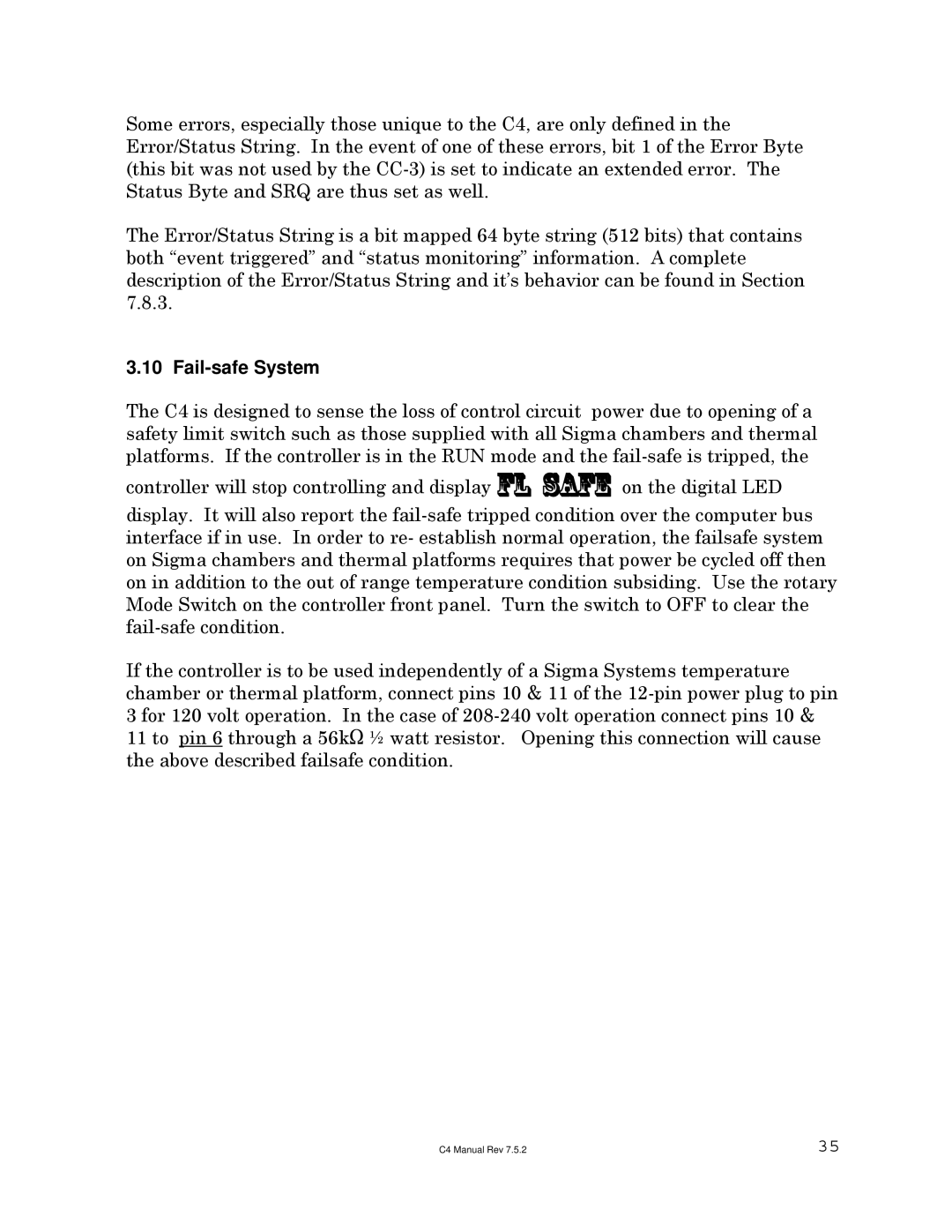
The C4 is designed to sense the loss of control circuit power due to opening of a safety limit switch such as those supplied with all Sigma chambers and thermal platforms. If the controller is in the RUN mode and the
controller will stop controlling and display fl safe on the digital LED
display. It will also report the
If the controller is to be used independently of a Sigma Systems temperature chamber or thermal platform, connect pins 10 & 11 of the
11 to pin 6 through a 56kS ½ watt resistor. Opening this connection will cause the above described failsafe condition.
C4 Manual Rev 7.5.2 | 35 |
