WR250FR
Page
WR250FR
Introduction
Page
Always Maintain Your Machine in Proper Working Order
Always Wear Protective Apparel
Properly Secure the Machine Before Transporting IT
Gasoline can Cause Injury
Park the Machine Carefully Turn OFF the Engine
Weights of machines without fuel
M. Machine Weights
Finding the Required
Particularly Important Information
Manual Format
HOW to Read Descriptions
GEN Spec Info Insp ENG ADJ
Memo
Index
Chapter Regular Inspection Adjustments
Valves and Valve Springs
SEAT, Fuel Tank
Right Crankcase Cover
AC Magneto
Throttle Position Sensor
Electrical Components
Description
Description Info
Vehicle Identification Number
Machine Identification
Engine Serial Number
Model Label
Important Information
Preparation for Removal and Disassembly
Lock WASHERS/PLATES and Cotter Pins
ALL Replacement Parts
GASKETS, OIL Seals and O-RINGS
Bearings and OIL Seals
Circlips
Checking of Connection
Special Tools
Part number Tool name/How to use Illustration
ACC-QUICK-GS-KT
Main switch indicator light
Main Switch
Engine Stop Switch
Start Switch
Shift Pedal
Clutch Lever
Kickstarter Crank
Throttle Grip
Fuel Cock
Rear Brake Pedal
Cold Starter Knob
HOT Starter Lever
Valve Joint
Light Switch
Spark Plug Wrench
Nipple Wrench
Fuel
Starting a Cold Engine
AIR Filter Maintenance
Starting and BREAK-IN
Do not warm up the engine for extended periods of time
Engine fails to start
Starting a Warm Engine
Restarting an engine after a fall
Cylinder and Crankshaft
BREAK-IN Procedures
About one hour of break-in operation is necessary
PISTON, RING, VALVES, Camshafts and Gears
TORQUE-CHECK Points
Cleaning
Cleaning and Storage
Storage
5UM4 CDN, AUS, NZ, ZA
General Specifications
FCR-MX37
CDI
Engine
Maintenance Specifications
Head diameter Face width Seat width Margin thickness
1.6 mm
Spec
USA EUROPE, CDN ZA, AUS, NZ
Spec
Part to be tightened Thread size ’ty Tightening torque
Silencer
USA, CDN Europe AUS, NZ, ZA
Chassis
USA, CDN, ZA EUROPE, AUS, NZ
Upper bracket and outer tube
Nipple spoke Rear wheel sprocket
M4 ⋅
5UL-00/DENSO
Electrical
ACM33221 M06/MATSUSHITA
Definition of Units
General Torque Specifications
Torque
Mkg Ftlb 10 mm 12 mm 14 mm 17 mm 19 mm 22 mm 16 mm 130
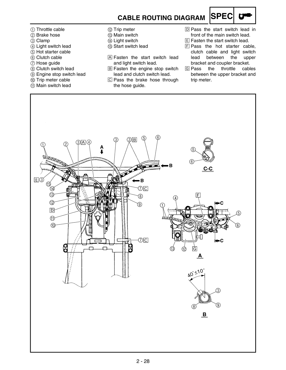
Cable Routing Diagram
Spec
Spec
Spec
Spec
Spec
Spec
Spec
Spec
Insp ADJ
Maintenance Intervals
Cooling System
Maintenance Intervals ADJ
Marked For USA
General Inspection and Maintenance
PRE-OPERATION Inspection and Maintenance
Do not remove the radiator cap when the engine is hot
Coolant Replacement
Engine
Coolant Level Inspection
Coolant Replacement
Fill Radiator Engine To specified level
Radiator CAP Opening Pressure Inspection
Radiator CAP Inspection
Radiator cap opening pressure KPa 1.1 kg/cm2, 15.6 psi
Clutch Adjustment
Cooling System Inspection
Standard pressure KPa 1.8 kg/cm2, 25.6 psi
Clutch lever free play adjustment steps
Throttle Cable Adjustment
Throttle Cable Adjustment
Throttle grip free play adjustment steps
Hot starter lever free play adjustment steps
HOT Starter Lever Adjustment
Throttle Lubrication
Hot starter lever free play a 3 ~ 6 mm 0.12 ~ 0.24
AIR Filter Cleaning
AIR Filter Cleaning
Insp ADJ
Engine OIL Level Inspection
Engine OIL Level Inspection
API Standard
Engine OIL Replacement
Engine OIL Replacement
Oil filter element cover 10 Nm 1.0 m kg, 7.2 ft lb
Replacement steps
Install Copper washer 1 New Oil strainer frame
OIL Pressure Inspection
Pilot Screw Adjustment
Valve Clearance Inspection and Adjustment
Engine Idling Speed Adjustment
Valve Clearance Inspection and Adjustment
40 mm
Pad range Pad Availability Increments 20 mm
Mm increments
Example
Last digit of pad Rounded value
Exhaust
Intake
Spark Arrester Cleaning For USA
Brake System AIR Bleeding
CHASSIS/BRAKE System AIR Bleeding
Chassis
Brake lever position adjustment steps
Front Brake Adjustment
Front Brake Adjustment
Front Brake PAD Inspection and Replacement
Rear Brake Adjustment
Bleed screw Nm 0.6 m kg, 4.3 ft lb
Front Brake PAD Inspection and Replacement
Do not reuse the drained brake fluid
Rear Brake PAD Inspection and Replacement
Rear Brake PAD Inspection and Replacement
Pad pin plug Nm 0.3 m kg, 2.2 ft lb
Brake pad thickness Mm 0.25 in Limit 1.0 mm 0.04
Pad pin 18 Nm 1.8 m kg, 13 ft lb
Brake Fluid Level Inspection
Rear Brake PAD Insulator Inspection
Sprockets Inspection
Sprockets INSPECTION/DRIVE Chain Inspection
Drive Chain Inspection
Drive chain length 10 links Limit 150.1 mm 5.91
Drive Chain Inspection
Drive Chain Slack Adjustment
Drive Chain Slack Adjustment
Drive chain slack adjustment steps
Drive chain slack 40 ~ 50 mm 1.6 ~ 2.0
Axle nut 125 Nm 12.5 m kg, 90 ft lb
Front Fork OIL Seal and Dust Seal Cleaning
Locknut 16 Nm 1.6 m kg, 11 ft lb
Front Fork Inspection
Front Fork Internal Pressure Relieving
Front Fork Rebound Damping Force Adjustment
Standard position 9 clicks out Clicks out
Front Fork Compression Damping Force Adjustment
Rear Shock Absorber Inspection
Rear Shock Absorber Inspection
Standard position 14 clicks out Clicks out
Rear Shock Absorber Spring Preload Adjustment
Standard position About 7 clicks out About 10 clicks out
Standard position About 9 clicks out About 10 clicks out
Rear Shock Absorber LOW Compression Damping Force Adjustment
Standard position About 1-1/4 turns out
Standard tire pressure KPa 1.0 kgf/cm2, 15 psi
Tire Pressure Check
Spokes Inspection and Tightening
Wheel Inspection
Steering Head Inspection Adjustment
Steering Head Inspection and Adjustment
Steering ring nut adjustment steps
Steering nut wrench YU-33975/90890-01403
Avoid over-tightening
Steering nut wrench
38 Nm 3.8 m kg, 27 ft lb
Lubrication
Lubrication
Spark Plug Inspection
Electrical
Spark plug gap ~ 0.8 mm 0.028 ~ 0.031
Ignition Timing Check
Ignition Timing Check
Battery Inspection and Charging
Battery Inspection and Charging
Keep Batteries and Electrolyte OUT of Reach of Children
First AID in Case of Bodily Contact External
Remove Battery band
Example
Measurement steps
Charge Battery
Charging method using a variable voltage charger
Charging method using a constant voltage charger
Battery Replacement
Battery REPLACEMENT/FUSE Inspection
First, connect the positive lead 1, then the negative lead
Recommended lubricant Lithium soap base grease
Items Amperage rating ’ty
Fuse Inspection
Pocket tester YU-3112-C/90890-03112
Replacing the Headlight Bulbs
Adjusting the Headlight Beams
Adjusting steps
SEAT, Fuel Tank and Side Covers Removal
SEAT, Fuel Tank and Side Covers
Side cover
Removal Points
Exhaust Pipe Silencer Removal
Exhaust Pipe and Silencer
Silencer and exhaust pipe
Assembly and Installation Silencer and exhaust pipe
Radiator Removal
Radiator
Radiator
Assembly and Installation Radiator
Handling Note
Install Right radiator Bolt right radiator
Carburetor Removal
Carburetor
Carburetor Disassembly
Carburetor Disassembly
ENG
Carburetor
Pilot screw
Throttle valve
Needle valve
Jet needle
Standard clip position No.4 Groove
Float
Float height Mm 0.31 Measurement and adjustment steps
Float height
Starter plunger
Assembly and Installation Carburetor
Accelerator pump
Air cut valve
ENG
ENG
Pilot screw Turns out example 8 turns out
ENG
Throttle valve height Mm 0.06
Accelerator pump timing adjustment Adjustment steps
Carburetor installation
Carburetor ENG
Carburetor ENG
Cylinder Head Cover Removal
Camshafts
Cylinder Head Cover
Camshafts Removal
Camshafts
Camshaft
Runout camshaft Less than 0.03 mm 0.0012
Bolt camshaft cap 10 Nm 1.0 m kg, 7.2 ft lb
Installation steps
Assembly and Installation Camshaft
Decompression system
Timing chain tensioner
CA U TI O N
Tensioner cap bolt
Camshafts ENG
Bolt timing chain tensioner
Quick gasket ACC-QUICK-GS-KT Yamaha Bond No
Cylinder Head Removal
Cylinder Head
Cylinder head
Assembly and Installation Cylinder head
Valves and Valve Springs Removal
Valves and Valve Springs
Valve spring compressor YM-4019/90890-04019
Valve lifter and valve cotter
Valve
Margin thickness Intake Mm 0.0315 in Exhaust Mm 0.0276
Runout limit 01 mm 0.0004
Lapping steps
Valve spring
Combination of cylinder head and valve lifter
Assembly and Installation Valve and valve spring
Combination Cylinder head mark Valve lifter mark b Color
Yellow
Valve spring compressor YM-4019/90890-04019
Cylinder and Piston Removal
Cylinder and Piston
Piston pin puller set YU-1304/90890-01304
Piston and piston ring
Do not use a hammer to drive the piston pin out
Cylinder and piston
05 mm 0.002
Cylinder bore C 77.00 ~ 77.01 mm 0315 ~ 3.0319
2nd step
Piston size P
Side clearance
Piston ring
Limit
End gap
Inside diameter piston 16.002 ~ 16.013 mm 0.6300 ~ 0.6304
Piston pin
Cylinder
Install Bolt cylinder
Clutch Removal
Clutch
ENG
Clutch boss
Clutch housing and boss
Clutch holding tool YM-91042/90890-04086
Primary driven gear
Clutch plate
Friction plate
Warp limit Mm 0.004 Push lever shaft
Push rod
Clutch
Assembly and Installation Push lever shaft
ENG
Install Push rod 2 Ball Push rod 1
OIL Filter ELEMENT, Water Pump and Right Crankcase Cover
ENG
Oil delivery pipe
Impeller shaft
Oil seal
Bearing
Assembly and Installation Oil seal
Impeller shaft gear
Right crankcase cover
Kickstarter crank
Oil filter element
Water pump housing
Balancer Removal
Balancer
Balancer shaft
Balancer shaft drive gear and balancer shaft driven gear
Primary drive gear Nut primary drive gear
OIL Pump
OIL Pump Removal and DIS Assembly
ENG
Oil pump
Assembly and Installation Oil pump
Bolt oil pump assembly L = 30 mm 1.18
Kick Shaft and Shift Shaft Removal
Kick Shaft and Shift Shaft
ENG
Shift guide and shift lever assembly
Kick shaft assembly
Segment
Kick shaft and ratchet wheel
Stopper lever
Assembly and Installation
Shift shaft
Install Torsion spring Stopper lever Bolt stopper lever
Kick shaft assembly
Kick idle gear
AC Magneto and Stator Removal
AC Magneto and Starter Clutch
ENG
Rotor puller YM-04141/90890-04141
Rotor
AC magneto
Woodruff key
Assembly and Installation AC magneto and starter clutch
Install Holder Bolt
Plain washer rotor Nut rotor
Bolt engine guard rear
Engine Removal
Engine Removal
ENG
Engine removal
Drive sprocket
Brake pedal
Assembly and Installation Engine installation
Oil hose and neutral switch
Nm 0.4 m · kg, 2.9 ft · lb
Crankcase and Crank Shaft Removal
Crankcase and Crankshaft
ENG
Crankcase Bearing Removal
Crankcase Bearing
Separation steps
Crankcase
Timing chain and timing chain guide
Crankshaft
Crankcase separating tool YU-1135-A/90890-01135
Dial gauge and stand YU-3097/90890-01252 Standard Limit
Do not use a hammer to drive in the crank- shaft
Assembly and Installation Crankcase bearing
Apply Sealant On the right crankcase
Tighten Hose guide Clutch cable holder Bolt crankcase
TRANSMISSION, Shift CAM Shift Fork Removal
TRANSMISSION, Shift CAM and Shift Fork
Gears
Transmission
Shift fork, shift cam and segment
Assembly and Installation Transmission
ENG
ENG
Front Wheel and Rear Wheel
Front Wheel and Rear Wheel Chas
Front Wheel
Front Wheel Removal
Rear Wheel Removal
Rear Wheel
Wheel
Rear wheel
Wheel bearing if necessary
Wheel axle bending limit 0.5 mm 0.020
Wheel axle
Do not attempt to straighten a bent axle
Brake disc
Front wheel
105 Nm 10.5 m · kg, 75 ft · lb
Tighten Bolt axle holder
Install Trip meter cable
50 Nm 5.0 m · kg, 36 ft · lb
125 Nm 12.5 m · kg, 90 ft · lb
Front Brake and Rear Brake
Front Brake and Rear Brake Chas
Front Brake
Front Brake Removal
Rear Brake Removal
Rear Brake
Brake Caliper Disassem BLY
Brake Caliper Disassembly
Brake Master Cylinder Disassembly
Brake Master Cylinder Disassembly
Brake fluid
Use only new brake fluid
Brake caliper piston seal kit
Brake master cylinder
Brake hose
Brake caliper
Front brake caliper
Always use new piston seals and dust seals
Rear brake caliper
Brake master cylinder kit
Front brake master cylinder
Rear brake master cylinder
Front brake hose
Always use new copper washers
CAU TI on
CAU T ION
Install rear brake only Protector Bolt protector
Front Fork Removal
Front Fork Chas
Front Fork
Front Fork Disassembly
Front Fork Disassembly
Front fork cap bolt
Take care not to scratch the inner tube
Inner tube
Oil seal removal steps
Damper rod
Fork spring
Base valve
Fork spring free length 460 mm 18.1 in Limit 455 mm 17.9
Inner tube bending limit 0.2 mm 0.008
Assembly and Installation Front fork assembly
Front Fork Chas
Fork seal driver YM-01442/90890-01442
Front Fork Chas
Front Fork Chas
Front Fork Chas
Front fork top end standard a 5 mm 0.20 10 mm 0.39
Installation
Tighten Pinch bolt upper bracket
Handlebar Removal
Handlebar Chas
Handlebar
Handlebar
Grip
Assembly and Installation Handlebar
Install Grip cap cover Cover throttle cable cap
Hot starter lever holder Bolt hot starter lever holder
Handlebar Chas
Steering Removal
Steering Chas
Steering
Steering Chas
Take care not to damage the steering shaft thread
Steering ring nut
Ball race
Steering stem
Lower bracket
Bearing and ball race
Install Washer Steering ring nut
Install Washer Steering stem nut
Install Trip meter Bolt trip meter
Swingarm Removal
Swingarm Chas
Swingarm
Swingarm Disassembly
Swingarm Disassembly
Relay arm
Swingarm
Bearing and oil seal
Connecting rod
Installed depth of bearings a 5 mm 0.20 Swingarm
Installed depth of bearings a 5 mm 0.20
80 Nm 8.0 m · kg, 58 ft · lb
Tighten Nut relay arm
Bolt drive chain support cover = 10 mm 0.39
Rear Shock Absorber Removal
Rear Shock Absorber Chas
Rear Shock Absorber
Starting circuit cut-off relay coupler
Handling Note
Rear shock absorber
Install Spring Upper spring guide Lower spring guide
Tighten Adjuster Spring length installed a
Bolt rear frame lower
Rear Shock Absorber Chas
Color Code
Electrical Components and Wiring Diagram
Wiring Diagram
Function of Component
MAP-CONTROLLED CDI Unit
Inspection Steps
Ignition System
Ignition System Elec +
Engine Stop Switch Inspection
Spark GAP Test
COUPLERS, Leads and Ignition Coil Connection Inspection
Tester + lead → Red lead Tester lead → Brown lead
Main Switch Inspection
Battery + lead → Red/Black lead 1 Battery lead → Black lead
Resistance Position ~ 6.8 kΩ at
Ignition Coil Inspection
Resistance Position 08 ~ 0.10 Ω at 20 C 68 F
AC Magneto Inspection
Neutral Switch Inspection
Resistance Position 248 ~ 372 Ω at 20 C 68 F
Tester + lead → Sky blue lead 1 Tester lead → Ground
Starting Circuit CUT-OFF System Operation
Electric Starting System
Inspection Steps
To battery
Battery
Couplers and Leads Connection Inspection
Starter Motor Operation
Pull Free
Clutch Switch Inspection
Starter Relay Inspection
Diode Inspection
Start Switch Inspection
Electric Starting System Elec +
Starter Motor Disassem BLY
Starter Motor
Starter Motor Removal
Mica undercut 1.5 mm 0.06
Inspection and Repair
Min. commutator diameter 16.6 mm 0.65
Min. brush length Mm 0.14
Assembly
Be careful not to damage the brush during installation
New
Charging System
Tester + lead → Red lead Tester lead → Black lead
Charging Voltage Inspection
Voltage Position 14.1 ~ 14.9 V at DCV-20 000 r/min
Resistance Position 288 ~ 0.432 Ω at 20 C 68 F
Throttle Position Sensor System
~ 6 kΩ at
Throttle Position Sensor System Elec +
Throttle Position Sensor Coil Inspection
At 20 C 68 F
Throttle Position Sensor Replacement and Adjustment
Coil variable resistance
Throttle position Tester selector
Tester + lead → Yellow lead Tester lead → Black lead
58 ~ 0.78
DCV
~ 6 DCV-20
Throttle Position Sensor Input Voltage Inspection
Lighting System
RECTIFIER/REGULATOR Inspection
Light Switch Inspection
OFF
Carburetor setting
Setting
Settings
Pilot system
Effects of the setting parts on the throttle valve opening
Main system
Effects of changing the main jet reference
Main jet adjustment
Standard main jet #185 #172
Setting T U N
Jet needle groove position adjustment
Effects of adjusting the pilot jet reference
Standard jet needle
Jet needle adjustment
Obdvs Obelp
Effects of changing the jet needle reference
Standard leak jet #90 Relationship with throttle opening
Leak jet adjustment accelerator pump adjustment
STD
Examples of carburetor setting depending on symptom
Standard secondary reduction ratio 52/13
Selection of the secondary reduction ratio Sprocket
5GS-25448-50
9383B-13218
Sprocket
5NY-25448-00
Change in level and characteristics of fork oil
Front fork setting
Spring preload adjustment
Setting of spring after replacement
Spring
Part Number
Mark
Rate
Standard figure 90 ~ 100 mm 3.5 ~ 3.9
Rear suspension setting
Choosing set length
Setting of spring after replacement
Setting
Spring Free Extent
Rear shock absorber setting parts
Adjustment b
Suspension setting
One passenger is astride seat
Printed on Recycled Paper Shingai Iwata Shizuoka Japan