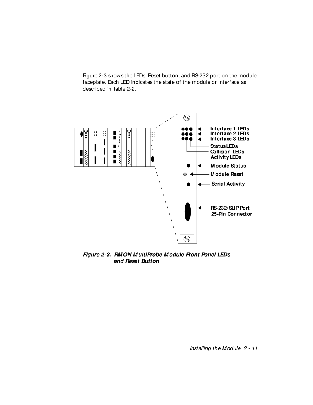
Figure 2-3 shows the LEDs, Reset button, and RS-232 port on the module faceplate. Each LED indicates the state of the module or interface as described in Table 2-2.
Interface 1 LEDs |
Interface 2 LEDs |
Interface 3 LEDs |
Status LEDs |
Collision LEDs |
Activity LEDs |
Module Status |
Module Reset |
Serial Activity |
Figure 2-3. RMON MultiProbe Module Front Panel LEDs and Reset Button
Installing the Module 2 - 11