Powered by Accton
Page
Fast Ethernet Switch
ES3526XA ES3552XA F2.2.6.3 E122006-CS-R02 149100005500H
Contents
Page
Iii
Page
Command Line Interface
Page
Vii
Viii
Contents
Page
Contents
Xii
Appendix a Software Specifications
Appendix B Troubleshooting
Glossary Index
Xiii
Xiv
Tables
Xvi
Xvii
Xviii
Figures
Xix
Figures
Xxi
Xxii
Key Features
Key Features
Feature Description
Supports standard STP and Rapid Spanning Tree Protocol Rstp
Description of Software Features
Description of Software Features
Introduction
System Defaults
System Defaults
Function Parameter Default
Password super
System Defaults Function Parameter
Client Enabled
Clock Synchronization Disabled
Introduction
Connecting to the Switch
Configuration Options
Initial Configuration
Required Connections
Basic Configuration
Remote Connections
Console Connection
Setting Passwords
Setting an IP Address
Manual Configuration
Dynamic Configuration
Enabling Snmp Management Access
Community Strings for Snmp version 1 and 2c clients
Trap Receivers
118
120
Saving Configuration Settings
Configuring Access for Snmp Version 3 Clients
125
126
Managing System Files
Initial Configuration
Configuring the Switch
Using the Web Interface
Navigating the Web Browser Interface
Home
Configuration Options
Panel Display
Configuration
Main Menu
Main Menu
Menu Description System System Information
Menu Description
ACL
139
Current Table
143
148
Class-of-service value IP Dscp Priority
155
164
Dscp Priority Status Both IP Precedence Priority
Menu Description Igmp Snooping 170 Igmp Configuration
Query Igmp Filter Configuration
Configuration Settings Igmp Filter/Throttling Trunk
Configuration Settings
Main Menu
Displaying System Information
Field Attributes
Displaying Switch Hardware/Software Versions
Main Board
Management Software
Expansion Slot
Displaying Switch Information
Bridge Extension Configuration
Displaying Bridge Extension Capabilities
Setting the Switch’s IP Address
CLI Enter the following command
Command Attributes
195
131
244
245
Using DHCP/BOOTP
246
Command Usage
Dhcp Relay and Option 82 Information
241
242
Managing Firmware
Downloading System Software from a Server
Operation Code Image File Transfer
11 Deleting Files
Saving or Restoring Configuration Settings
Downloading Configuration Settings from a Server
12 Copy Configuration Settings
Console Port Settings
14 Console Port Settings
Telnet Settings
15 Enabling Telnet
Configuring Event Logging
System Log Configuration
Logging Levels
Level Severity Name Description
Remote Log Configuration
17 Remote Logs
Displaying Log Messages
CLI This example shows the event message stored in RAM
Sending Simple Mail Transfer Protocol Alerts
19 Enabling and Configuring Smtp Alerts
Resetting the System
20 Resetting the System
Setting the System Clock
Configuring Sntp
Configuring NTP
22 NTP Client Configuration
Setting the Time Zone
Simple Network Management Protocol
SNMPv3 Security Models and Levels
Level Group Read View Write View Notify View Security
User defined
Setting Community Access Strings
CLI The following example enables Snmp on the switch
Enabling the Snmp Agent
117
25 Configuring Snmp Community Strings
Specifying Trap Managers and Trap Types
Configuring the Switch
Configuring SNMPv3 Management Access
122
Setting a Local Engine ID
Specifying a Remote Engine ID
CLI This example sets an SNMPv3 engine ID
123
Configuring SNMPv3 Users
CLI This example specifies a remote SNMPv3 engine ID
29 Configuring SNMPv3 Users
Configuring Remote SNMPv3 Users
130
30 Configuring Remote SNMPv3 Users
Configuring SNMPv3 Groups
Supported Notification Messages
Private Traps SwPowerStatus
This trap is sent when the fan fails
SwFanRecoverTrap
This trap is sent when the fan failure has
31 Configuring SNMPv3 Groups
127
Setting SNMPv3 Views
32 Configuring SNMPv3 Views
User Authentication
Configuring User Accounts
33 Access Levels
Configuring Local/Remote Logon Authentication
Radius Settings
Tacacs Settings
34 Authentication Settings
Configuring Https
Https System Support
Replacing the Default Secure-site Certificate
Address server ip-address
Configuring the Secure Shell
Configuring the Switch
Generating the Host Key Pair
36 SSH Host-Key Settings
Configuring the SSH Server
SSH server includes basic settings for authentication
Configuring Port Security
38 Configuring Port Security
Configuring 802.1X Port Authentication
Displaying 802.1X Global Settings
802.1X protocol provides client authentication
CLI This example shows the default global setting for
Web Click Security, 802.1X, Information
Configuring 802.1X Global Settings
Configuring Port Settings for
CLI This example enables 802.1X globally for the switch
41 802.1X Port Configuration
Authorized
Consoleconfig#interface ethernet 1/2
Displaying 802.1X Statistics
802.1X Statistics
MAC Address Authentication
CLI This example displays the 802.1X statistics for port
Configuring the MAC Authentication Reauthentication Time
Configuring MAC Authentication for Ports
Web Click Security, Network Access, Configuration
Web Click Security, Network Access, Port Configuration
CLI This example configures MAC authentication for port
Displaying Secure MAC Address Information
45 Network Access MAC Address Information
Configuring MAC Address Filters
100
Filtering Addresses for Management Access
CLI This example allows Snmp access for a specific client
47 Creating a Web IP Filter List
Access Control Lists
Configuring Access Control Lists
Setting the ACL Name and Type
CLI This example creates a standard IP ACL named david
103
Configuring a Standard IP ACL
104
Configuring an Extended IP ACL
50 ACL Configuration Extended IP
105
Configuring a MAC ACL
111
Binding a Port to an Access Control List
52 Binding a Port to an ACL
Port Configuration
Displaying Connection Status
Field Attributes Web
107
Configuration
Web Click Port, Port Information or Trunk Information
Basic Information
Configuring Interface Connections
Current Status
138
54 Port/Trunk Configuration
Creating Trunk Groups
136
135
Statically Configuring a Trunk
55 Configuring Port Trunks
Enabling Lacp on Selected Ports
147
56 Lacp Configuration
148
Configuring Lacp Parameters
Dynamically Creating a Port Channel
57 Lacp Aggregation Port
Displaying Lacp Port Counters
You can display statistics for Lacp protocol messages
Lacp Port Counters
Protocols Ethernet Type
LACPDUs Illegal Pkts
Displaying Lacp Settings and Status for the Local Side
Lacp Internal Configuration Information
Field Description
59 Lacp Port Internal Information
Displaying Lacp Settings and Status for the Remote Side
10 Lacp Neighbor Configuration Information
Console#show lacp 1 neighbors
Setting Broadcast Storm Thresholds
61 Port Broadcast Control
Configuring Port Mirroring
137
140
Configuring Rate Limits
Rate Limit Granularity
142
Rate Limit Configuration
145
Showing Port Statistics
144
Transmit Errors
Errors
FCS Errors
Protocol
11 Port Statistics
Parameter Description
Rmon Statistics
Or alignment error
Fragments
65 Port Statistics
Address Table Settings
Setting Static Addresses
CLI This example shows statistics for port
139
Displaying the Address Table
157
67 Dynamic Addresses
158
Spanning Tree Algorithm Configuration
Changing the Aging Time
CLI This example sets the aging time to 300 seconds
159
Designated Root Port Bridge
Displaying Global Settings
For this Region
120
69 STA Information
176
Mstp
Configuring Global Settings
Global settings apply to the entire switch
Basic Configuration of Global Settings
Root Device Configuration
Configuration Settings for Rstp
Configuration Settings for Mstp
70 STA Global Configuration
Displaying Interface Settings
AD B
71 STA Port Information
Configuring Interface Settings
CLI This example shows the STA attributes for port
131
Configuring Multiple Spanning Trees
CLI This example sets STA attributes for port
133
73 Mstp Vlan Configuration
178
167
Displaying Interface Settings for Mstp
74 Mstp Port Information
Configuring Interface Settings for Mstp
CLI This example sets the Mstp attributes for port
175
174
Vlan Configuration
Ieee 802.1Q VLANs
Assigning Ports to VLANs
VA Vlan Aware VU Vlan Unaware
Forwarding Tagged/Untagged Frames
Enabling or Disabling Gvrp Global Setting
CLI This example enables Gvrp for the switch
Displaying Basic Vlan Information
194
Command Attributes Web
Displaying Current VLANs
78 Vlan Current Table Command Attributes CLI
Creating VLANs
187
CLI This example creates a new Vlan
179
180
Adding Static Members to VLANs Vlan Index
Adding Static Members to VLANs Port Index
185
81 Vlan Static Membership by Port
Configuring Vlan Behavior for Interfaces
82 Vlan Port Configuration
Private VLANs
182
183
184
Displaying Current Private VLANs
153
Configuring Private VLANs
Associating VLANs
189
Displaying Private Vlan Interface Information
190
Configuring Private Vlan Interfaces
193
87 Private Vlan Port Configuration
191
Class of Service Configuration
Layer 2 Queue Settings
Setting the Default Priority for Interfaces
88 Port Priority Configuration
CLI This example assigns a default priority of 5 to port
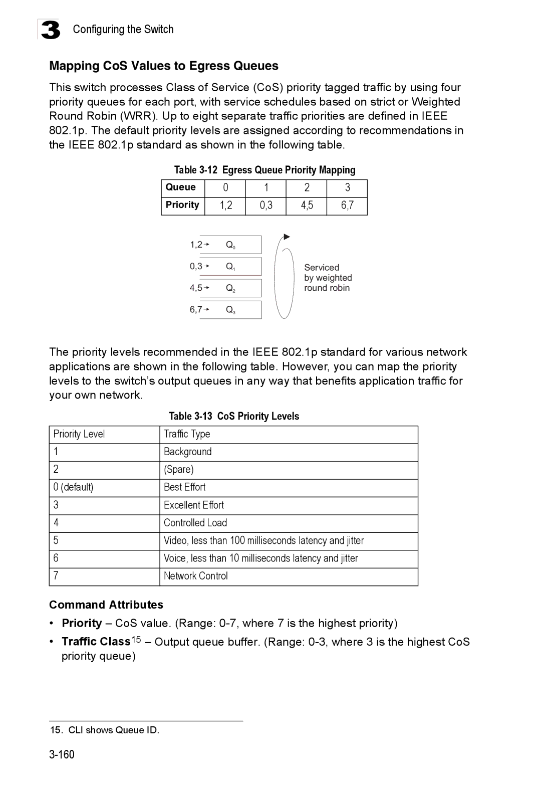
Mapping CoS Values to Egress Queues
12 Egress Queue Priority Mapping
13 CoS Priority Levels
201
203
Selecting the Queue Mode
90 Queue Mode
Setting the Service Weight for Traffic Classes
200
202
Layer 3/4 Priority Settings
Mapping Layer 3/4 Priorities to CoS Values
Selecting IP Precedence/DSCP Priority
204
Mapping IP Precedence
14 Mapping IP Precedence
Mapping Dscp Priority
15 Mapping Dscp Priority Values
206
209
207
210
Mapping IP Port Priority
95 IP Port Priority Status
Mapping CoS Values to ACLs
16 Egress Queue Priority Mapping
205
Multicast Filtering
108
Configuring Igmp Snooping and Query Parameters
Layer 2 Igmp Snooping and Query
98 Igmp Configuration
Enabling Igmp Immediate Leave
Displaying Interfaces Attached to a Multicast Router
100 Displaying Multicast Router Port Information
Specifying Static Interfaces for a Multicast Router
220
219
Displaying Port Members of Multicast Services
215
Assigning Ports to Multicast Services
103 Igmp Member Port Table
Igmp Filtering and Throttling
Enabling Igmp Filtering and Throttling
Configuring Igmp Filter Profiles
104 Enabling Igmp Filtering and Throttling
105 Igmp Profile Configuration
Configuring Igmp Filtering and Throttling for Interfaces
106 Igmp Filter and Throttling Port Configuration
General Configuration Guidelines for MVR
Multicast Vlan Registration
Configuring Global MVR Settings
107 MVR Global Configuration
Displaying MVR Interface Status
108 MVR Port Information
Displaying Port Members of Multicast Groups
109 MVR Group IP Information
Configuring MVR Interface Status
MVR Vlan
Web Click MVR, Port or Trunk Configuration
Assigning Static Multicast Groups to Interfaces
Configuring Domain Name Service
Configuring General DNS Service Parameters
190
234
235
236
237
Configuring Static DNS Host to Address Entries
113 DNS Static Host Table
Displaying the DNS Cache
233
238
Switch Clustering
Cluster Configuration
Cluster Member Configuration
Adds Candidate switches to the cluster as Members
249
250
Web Click Cluster, Member Configuration
Displays current cluster Member switch information
Cluster Member Information
Cluster Candidate Information
253
Configuring the Switch 198
Using the Command Line Interface
Accessing the CLI
Telnet Connection
Command Line Interface
Entering Commands
Command Completion
Getting Help on Commands
Keywords and Arguments
Showing Commands
CLIMSGPRIVILEGEEXECCMDW2SHOWMVR
Negating the Effect of Commands
Using Command History
Understanding Command Modes
Partial Keyword Lookup
Exec Commands
Command Modes
Configuration Commands
Configuration Modes Command Prompt
Consoleconfig-if# 131
Spanning-tree mst-configuration Consoleconfig-mstp# 160
Command Line Processing
Command Line Processing
Keystroke Function
Command Groups
Command Groups Description
Command Line Interface
Line Commands
Line
Login
Related Commands
Syntax Login local no login
Example
Password
Username 4-27 password
Syntax Password 0 7 password no password
No password is specified
Timeout login response
Exec-timeout
Syntax Exec-timeout seconds no exec-timeout
Password-thresh
Silent-time4-16 Timeout login response
Syntax Password-thresh threshold no password-thresh
Default value is three attempts
Silent-time
Databits
Syntax Silent-time seconds no silent-time
Syntax Databits 7 8 no databits
Parity
Syntax Parity none even odd no parity
Speed
Stopbits
Syntax Speed bps no speed
Syntax Stopbits 1
Disconnect
Show line
Syntax Disconnect session-id
Syntax Show line console vty
General Commands
Enable
To show all lines, enter this command
General Commands Function Mode
Disable
Disable Enable password
Enable
Level
Configure
Show history
Reload
End
This command exits the configuration program
This example shows how to quit a CLI session
Exit
Quit
System Management Commands
Device Designation Commands
Prompt
User Access Commands
User Access Commands Function Mode
Hostname
Syntax Hostname name no hostname
10 Default Login Settings Username Access-level Password
Guest Admin
Username
Enable password
Default is level Default password is super
Enable 4-20 authentication enable
IP Filter Commands
11 IP Filter Commands Function Mode
Management
Management
Show management
Web Server Commands
Ip http port
Ip http server
Syntax No ip http secure-server Default Setting
Ip http secure-server
Ip http port
13 Https System Support Web Browser Operating System
Ip http secure-port
Ip http secure-port4-33 Copy tftp https-certificate
Portnumber The UDP port used for HTTPS/SSL. Range
Ip http secure-server4-32
Telnet Server Commands
Ip telnet port
Ip telnet server
Secure Shell Commands
15 SSH Commands Function Mode
Ip telnet port
Sets the SSH server key size Copy tftp public-key
Command Line Interface
Syntax No ip ssh server Default Setting
Ip ssh server
Ip ssh crypto host-key generate 4-40 show ssh
Ip ssh timeout
Ip ssh authentication-retries
Syntax Ip ssh timeout seconds no ip ssh timeout
Exec-timeout4-14 show ip ssh
Ip ssh server-key size
Delete public-key
Syntax Delete public-key username dsa rsa
Ip ssh crypto host-key generate
Ip ssh crypto zeroize
Syntax Ip ssh crypto host-key generate dsa rsa
Syntax Ip ssh crypto zeroize dsa rsa
Ip ssh save host-key
Show ip ssh
Syntax Ip ssh save host-key dsa rsa
Show ssh
16 show ssh display description
Terminology
Show public-key
Syntax Show public-key user username host
Username Name of an SSH user. Range 1-8 characters
Shows all public keys
Event Logging Commands
17 Event Logging Commands Function Mode
Syntax No logging on Default Setting
Logging on
Flash errors level 3 RAM warnings level 6
Logging history
18 Logging Levels
Logging host
Logging facility
Syntax No logging host hostipaddress
Hostipaddress The IP address of a syslog server
Logging trap
Clear logging
Syntax Logging trap level no logging trap
Syntax Clear logging flash ram
Show logging
Syntax Show logging flash ram sendmail trap
19 show logging flash/ram display description
Facility command
Logging trap command
Syntax Show log flash ram login tail
Show log
Smtp Alert Commands
21 Smtp Alert Commands Function Mode
Logging sendmail host
Following example shows sample messages stored in RAM
Logging sendmail level
Syntax Logging sendmail level level
Logging sendmail source-email
Logging sendmail destination-email
Syntax No logging sendmail source-email email-address
This example will set the source email john@acme.com
Syntax No logging sendmail Default Setting
Logging sendmail
Show logging sendmail
Time Commands
22 Time Commands Function Mode
Syntax No sntp client Default Setting
Sntp client
Sntp server
Sntp server 4-55 sntp poll 4-56 show sntp
Syntax Sntp server ip1 ip2 ip3
Ip IP address of an NTP time server. Range 1-3 addresses
Sntp poll
Show sntp
Syntax Sntp poll seconds no sntp poll
Syntax No ntp client Default Setting
Ntp client
Ntp server
Sntp client 4-54 ntp poll 4-58 ntp server
Ntp poll
Version number
Ntp client 4-57 ntp poll 4-58 show ntp
Syntax Ntp poll seconds no ntp poll
Ntp authenticate
Ntp authentication-key
Syntax No ntp authenticate Default Setting
Ntp authentication-key4-59
Show ntp
Clock timezone
This command displays the system clock
Calendar set
Show calendar
Calendar set hour min sec day month year month day year
System Status Commands
Show startup-config
23 System Status Commands Function Mode
Show running-config4-65
Show running-config
Show startup-config4-63
This command displays system information
Show system
Show users
Show version
Frame Size Commands
24 Frame Size Commands
Jumbo frame Enables support for jumbo frames
Syntax No jumbo frame Default Setting
Flash/File Commands
25 Flash/File Commands
Command Function Mode Copy
Flash/File Commands
Following example shows how to download a configuration file
Syntax Dir boot-rom config opcode filename
Delete
Dir
Delete filename
Whichboot
Syntax whichboot Default Setting
26 File Directory Information
Column Heading Description
Boot system
Syntax Boot system boot-romconfig opcode filename
Dir 4-73 whichboot
Authentication Commands
Authentication Sequence
Authentication login
27 Authentication Commands Command Group Function
Authentication enable
Username for setting the local user names and passwords
29 Radius Client Commands Function Mode
Show radius-server Shows the current Radius settings
Radius Client
Radius-server host
Radius-server port
Radius-server key
Radius-server timeout
Radius-server retransmit
30 Tacacs Commands Function Mode
TACACS+ Client
Show radius-server
Tacacs-server host
Tacacs-server port
Tacacs-server key
Syntax Tacacs-server port portnumber no tacacs-server port
Show tacacs-server
Syntax Tacacs-server key keystring no tacacs-server key
Port Security Commands
31 Port Security Commands Function Mode
Status Disabled Action None Maximum Addresses
Interface Configuration Ethernet
802.1X Port Authentication
32 802.1X Port Authentication Command Function Mode
Dot1x default
Acquire a new client Dot1x timeout re-authperiod
Be re-authenticated Dot1x timeout tx-period
Syntax No system-auth-control Default Setting
Default Command Mode
Dot1x max-req
Dot1x port-control
Syntax Dot1x max-req count no dot1x max-req
Dot1x re-authenticate
Syntax Dot1x re-authenticate interface
Dot1x operation-mode
Interface
Dot1x re-authentication
Dot1x timeout quiet-period
Syntax No dot1x re-authentication Command Mode
Seconds The number of seconds. Range
Dot1x timeout re-authperiod
Dot1x timeout tx-period
Show dot1x
Syntax Show dot1x statistics interface interface
Statistics Displays dot1x status for each port
Authenticator State Machine
Reauthentication State Machine
State Current state including initialize, reauthenticate
Backend State Machine
Example
Network Access
Network-access mode
33 Network Access Command Function Mode
Network-access max-mac-count
1024
Network-access mac-filter
Syntax No network-access mac-filter filter-idmac-address
Network-access port-mac-filter
Network-access dynamic-vlan
Syntax No network-access dynamic-vlan Default Setting
Filter-id- The number that identifies the filter. Range
Mac-authentication reauth-time
Following example enables dynamic Vlan assignment on port
1800
Clear network-access
Show network-access
Syntax Show network-access interface interface
Displays the settings for all interfaces
Show network-access mac-filter
Show network-access mac-address-table
Use this command to display MAC authentication filters
Displays all filters
101
Access Control List Commands
Access Control Lists
Access-list ip
34 Access Control Lists Command Groups Function
35 IP ACLs Command Function Mode
Syntax No access-list ip standard extended aclname
Permit, deny Ip access-group4-107 show ip access-list4-107
Syntax No permit deny any source bitmask host source
Standard ACL
Access-list ip
No permit deny tcp
Extended ACL
Show ip access-list
Ip access-group
Syntax Show ip access-list standard extended aclname
Syntax No ip access-group aclname
Show ip access-group
Map access-list ip
Show ip access-list4-107
This command shows the ports assigned to IP ACLs
Show map access-list ip
Queue cos-map4-201 Show map access-list ip
Syntax Show map access-list ip interface
36 Egress Queue Priority Mapping Example
Access-list mac
37 MAC ACLs Command Function Mode
Syntax No access-list mac aclname
MAC ACLs
Permit, deny MAC ACL
Syntax No permit deny
Show mac access-list
Mac access-group
Syntax Show mac access-list aclname
Syntax Mac access-group aclname
Show mac access-group
Map access-list mac
Show mac access-list4-112
This command shows the ports assigned to MAC ACLs
Show map access-list mac
Queue cos-map4-201 Show map access-list mac
Syntax Show map access-list mac interface
38 Egress Queue Priority Mapping
Show access-list
Show access-group
39 ACL Information Command Function Mode
ACL Information
Snmp Commands
40 Snmp Commands Function Mode
Syntax No snmp-server Default Setting
Snmp-server
Show snmp
Snmp-server community
Snmp-server contact
Snmp-server location
Syntax Snmp-server contact string no snmp-server contact
Syntax Snmp-server location text no snmp-server location
Snmp-server host
Host Address None Notification Type Traps
Snmp Version UDP Port
Snmp-server enable traps
Snmp-server enable traps
Issue authentication and link-up-down traps
Snmp-server engine-id
This command shows the Snmp engine ID
This example shows the default engine ID
Show snmp engine-id
Defaultview includes access to the entire MIB tree
Snmp-server view
Examples
This view includes MIB-2
This command shows information on the Snmp views
Show snmp view
Snmp-server group
42 show snmp view display description
Show snmp group
Snmp-server user
43 show snmp group display description
129
This command shows information on Snmp users
Show snmp user
44 show snmp user display description
Interface Commands
45 Interface Commands Function Mode
Interface
Port-channel channel-idRange
Description
Speed-duplex
Syntax Description string no description
Syntax No negotiation Default Setting
Negotiation
Negotiation 4-133 capabilities
Following example configures port 11 to use autonegotiation
Capabilities
Capabilities 4-134speed-duplex4-132
Syntax No flowcontrol Default Setting
Flowcontrol
Negotiation 4-133speed-duplex4-132 flowcontrol
Syntax No shutdown Default Setting
Shutdown
Switchport broadcast packet-rate
This command clears statistics on an interface
Port-channel channel-idRange Default Setting
Clear counters
This command displays the status for an interface
Show interfaces status
Following example clears statistics on port
Syntax Show interfaces status interface
This command displays interface statistics
Show interfaces counters
Syntax Show interfaces counters interface
Shows the counters for all interfaces
Show interfaces switchport
Syntax Show interfaces switchport interface
Shows all interfaces
Interfaces Switchport Statistics
Mirror Port Commands
47 Mirror Port Commands Function Mode
Port monitor
Interface ethernet unit/port source port
This command displays mirror information
Following shows mirroring configured from port 6 to port
Show port monitor
Syntax Show port monitor interface
Rate Limit Commands
48 Rate Limit Commands Function Mode
Rate-limit
Fast Ethernet255 Gigabit Ethernet30
Global Configuration Ethernet, Port Channel
Use this command to display the rate limit granularity
Rate-limit granularity
Show rate-limit
Link Aggregation Commands
49 Link Aggregation Commands
151
138
Channel-group
Guidelines for Creating Trunks
General Guidelines
Dynamically Creating a Port Channel
Syntax No lacp Default Setting
Lacp
Following example creates trunk 1 and then adds port
Lacp system-priority
32768
Lacp admin-keyEthernet Interface
Lacp admin-key Port Channel
Interface Configuration Port Channel
This command displays Lacp information
Lacp port-priority
Show lacp
Port Channel all
50 show lacp counters display description
Type
Badly formed PDU or an illegal value of Protocol Subtype
51 show lacp internal display description
52 show lacp neighbors display description
Address Table Commands
54 Address Table Commands Function Mode
53 show lacp sysid display description
Mac-address-table static
Mac-address- MAC address
Vlan-id- Vlan ID Range
Action
Clear mac-address-table dynamic
Show mac-address-table
Mac-address- MAC address Mask Bits to match in the address
Mac-address-table aging-time
Show mac-address-table aging-time
Spanning Tree Commands
55 Spanning Tree Commands Function Mode
Spanning-tree mode
Syntax No spanning-tree Default Setting
Spanning tree is enabled
Spanning-tree
Spanning-tree forward-time
Spanning-tree hello-time
Spanning-tree forward-time 4-162spanning-tree max-age
Spanning-tree max-age
Spanning-tree priority
Spanning-tree forward-time 4-162spanning-tree hello-time
Spanning-tree pathcost method
Long method
Spanning-tree mst-configuration
This command limits the maximum transmission rate for BPDUs
Spanning-tree transmission-limit
Count The transmission limit in seconds. Range
MST Configuration
Mst vlan
No mst instanceid vlan vlan-range
Mst priority
Name
Mst instanceid priority priority no mst instanceid priority
Syntax Name name
Revision
Max-hops
Syntax Revision number
Max-hopshop-number
Spanning-tree spanning-disabled
Syntax No spanning-tree spanning-disabled Default Setting
This example disables the spanning tree algorithm for port
Spanning-tree cost
Spanning-tree port-priority
Priority The priority for a port. Range 0-240, in steps
Syntax No spanning-tree edge-port Default Setting
Spanning-tree edge-port
Syntax No spanning-tree portfast Default Setting
Spanning-tree portfast
Spanning-tree link-type
Spanning-treeedge-port4-172
Spanning-tree mst cost
Auto
Spanning-tree mst port-priority
Spanning-tree mst port-priority4-175
Port-channel channel-idRange Command Mode
Spanning-tree protocol-migration
Show spanning-tree
Syntax Spanning-tree protocol-migration interface
177
Show spanning-tree mst configuration
Vlan Commands
56 VLANs Command Groups Function
57 Editing Vlan Groups Command Function Mode
Editing Vlan Groups
By default only Vlan 1 exists and is active
Vlan Database Configuration
Vlan
Show vlan
Configuring Vlan Interfaces
58 Configuring Vlan Interfaces Command Function Mode
Interface vlan
Interface vlan
Switchport mode
Switchport acceptable-frame-types
All ports are in hybrid mode with the Pvid set to Vlan
Switchport acceptable-frame-types4-182
Switchport ingress-filtering
Syntax No switchport ingress-filtering Default Setting
Switchport native vlan
Switchport allowed vlan
Switchport forbidden vlan
59 Show Vlan Commands Function Mode
Displaying Vlan Information
This command shows Vlan information
Following example shows how to display information for Vlan
Show vlan
Shows all VLANs
Configuring Private VLANs
60 Private Vlan Commands
Vlan Configuration
Private-vlan
Private vlan association
No private-vlan primary-vlan-idassociation
Switchport mode private-vlan
Switchport private-vlan host-association
Normal Vlan
Secondary-vlan-id- ID of secondary VLAN. Range
Switchport private-vlan isolated
Isolated-vlan-id- ID of isolated VLAN. Range
Switchport private-vlan mapping
Show vlan private-vlan
Syntax Show vlan private-vlan community isolated primary
Gvrp and Bridge Extension Commands
61 Gvrp and Bridge Extension Commands Function Mode
Syntax No bridge-ext gvrp Default Setting
Bridge-ext gvrp
Switchport gvrp
Syntax No switchport gvrp Default Setting
Show bridge-ext
Show gvrp configuration
Garp timer
This command shows if Gvrp is enabled
Syntax Show gvrp configuration interface
Show garp timer
Syntax Show garp timer interface
Shows all Garp timers
Priority Commands
Priority Commands Layer
62 Priority Commands Command Groups Function
63 Priority Commands Layer Function Mode
Queue mode
Switchport priority default
Syntax Queue mode strict wrr no queue mode
Queue bandwidth weight1...weight4 no queue bandwidth
Queue bandwidth
Queue cos-map
Queue cos-mapqueueid cos1 ... cosn no queue cos-map
Show queue mode
This command shows the current queue mode
Show queue bandwidth
Show queue cos-map4-203
This command shows the class of service priority map
Show queue cos-map
Syntax Show queue cos-map interface
Priority Commands Layer 3
65 Priority Commands Layer 3 Function Mode
Syntax No map ip port Default Setting
Following example shows how to map Http traffic to CoS value
Syntax No map ip precedence Default Setting
List below shows the default priority mapping
66 Mapping IP Precedence Values CoS Value Command Mode
Syntax No map ip dscp Default Setting
Map ip dscp dscp-value cos cos-value no map ip dscp
Use this command to show the IP port priority map
Show map ip port
67 IP Dscp to CoS Vales IP Dscp Value CoS Value
10, 12, 14 18, 20, 22 26, 28, 30, 32, 34 38, 40
This command shows the IP precedence priority map
Show map ip precedence
Syntax Show map ip precedence interface
This command shows the IP Dscp priority map
Show map ip dscp
Syntax Show map ip dscp interface
Multicast Filtering Commands
Igmp Snooping Commands
68 Multicast Filtering Commands Command Groups Function
69 Igmp Snooping Commands Function Mode
Syntax No ip igmp snooping Default Setting
Following example enables Igmp snooping
Ip igmp snooping
Ip igmp snooping vlan static
Following configures the switch to use Igmp Version
Ip igmp snooping version
Ip igmp snooping immediate-leave
Igmp Version
Show ip igmp snooping
Show mac-address-table multicast
215
Igmp Query Commands Layer
70 Igmp Query Commands Layer Function Mode
Syntax No ip igmp snooping querier Default Setting
Ip igmp snooping querier
Following shows how to configure the query count to
Ip igmp snooping query-interval
Times
Ip igmp snooping query-max-response-time4-218
Seconds The report delay advertised in Igmp queries. Range
Ip igmp snooping query-max-response-time
Ip igmp snooping router-port-expire-time
Static Multicast Routing Commands
71 Static Multicast Routing Commands Function Mode
Ip igmp snooping vlan mrouter
Syntax No ip igmp snooping vlan vlan-idmrouter interface
Displays multicast router ports for all configured VLANs
Show ip igmp snooping mrouter
Syntax Show ip igmp snooping mrouter vlan vlan-id
Multicast router port types displayed include Static
Igmp Filtering and Throttling Commands
72 Igmp Filtering and Throttling Commands Function Mode
Syntax No ip igmp filter Default Setting
223
Syntax Permit deny Default Setting
Ip igmp profile
Permit, deny
Syntax No ip igmp profile profile-number
Range
No range low-ip-address high-ip-address
Syntax No ip igmp filter profile-number
Ip igmp max-groups
Syntax Ip igmp max-groups number No ip igmp max-groups
Ip igmp max-groups action
Show ip igmp filter
Syntax Ip igmp max-groups action replace deny
Syntax Show ip igmp filter interface
Show ip igmp profile
Show ip igmp throttle interface
Syntax Show ip igmp profile profile-number
Syntax Show ip igmp throttle interface interface
Multicast Vlan Registration Commands
73 Multicast Vlan Registration Commands Function Mode
229
Multicast groups assigned to the MVR Vlan
Command Line Interface Mvr Global Configuration
No mvr group ip-address count vlan vlan-id
Multicast Filtering Commands Mvr Interface Configuration
Show mvr
Syntax Show mvr interface interface members ip-address
Unit Stack unit. Range Port Port number. Range
Following shows the global MVR settings
74 show mvr display description
Are satisfied
75 show mvr interface display description
Domain Name Service Commands
77 DNS Commands Function Mode
76 show mvr members display description
Ip host
Clear host
No ip host name address1 address2 … address8
Syntax Clear host name
Ip domain-name
Removes all entries
This example clears all static entries from the DNS table
Syntax Ip domain-name name no ip domain-name
Ip domain-list
Syntax No ip domain-list name
Ip domain-name4-234
Ip name-server
Ip domain-lookup
Server-address1- IP address of domain-name server
Ip domain-name4-234 ip domain-lookup4-236
Show hosts
Ip domain-name4-234 ip name-server4-236
Show dns
Show dns cache
78 show dns cache display description
This command clears all entries in the DNS cache
Clear dns cache
Dhcp Commands
79 Dhcp Commands Function Mode
Syntax No ip dhcp relay information option Default Setting
Ip dhcp relay information option
Ip dhcp relay information policy
Ip dhcp relay server
Syntax Ip dhcp relay information policy drop keep replace
Ip dhcp relay server address1 address2 address3
Show ip dhcp-relay
Usage Guidelines
IP Interface Commands
80 IP Interface Commands Function Mode
Ip address
Ip default-gateway
Syntax Ip default-gateway gateway no ip default-gateway
Gateway IP address of the default gateway
No static route is established
Ip dhcp restart
Show ip interface
Ip default-gateway4-244
This command has no default for the host
Show ip redirects
Ping
247
Switch Cluster Commands
81 Switch Cluster Commands Function Mode
Syntax No cluster Default Setting
Cluster
Cluster commander
Syntax No cluster commander Default Setting
Cluster ip-pool
Syntax Cluster ip-pool ip-addressno cluster ip-pool
Rcommand
Syntax Rcommand id member-id
Member-id- The ID number of the Member switch. Range
Cluster member
This command shows the switch clustering configuration
This command shows the current switch cluster members
Show cluster
Show cluster members
Show cluster candidates
Appendix a Software Specifications
Software Features
Management Features
Groups 1, 2, 3, 9 Statistics, History, Alarm, Event
Standards
Management Information Bases
Software Specifications
Table B-1 Troubleshooting Chart
Symptom Action
Using System Logs
Access Control List ACL
Boot Protocol Bootp
Class of Service CoS
Differentiated Services Code Point Service Dscp
Garp Vlan Registration Protocol Gvrp
Generic Attribute Registration Protocol Garp
Generic Multicast Registration Protocol Gmrp
Group Attribute Registration Protocol Garp
Igmp Snooping
Igmp Query
Internet Group Management Protocol Igmp
In-Band Management
Multicast Switching
Port Authentication
Remote Authentication Dial-in User Service Radius
MD5 Message-Digest Algorithm
Remote Monitoring Rmon
Rapid Spanning Tree Protocol Rstp
Secure Shell SSH
Simple Network Management Protocol Snmp
User Datagram Protocol UDP
Virtual LAN Vlan
XModem
Index
Numerics
Gateway, default 3-14,4-245
Garp Vlan Registration Protocol See
Index-3
Index-4
Page
ES3526XA ES3552XA E122006-CS-R02D 149100005500H