SPECIFICATION & OPTIONS |
|
OPTIONS | A number of options are available for the | |||||
|
| The options are described in the following pages. Some of | ||||
|
| these options require changes to the firmware or hardware | ||||
|
| and some are only available when ordered at the time of | ||||
|
| initial order. |
|
|
|
|
|
| Serial Interfaces only need a change to switch and / or | ||||
|
| connector positions within the INTRAC. |
|
| ||
Voltage | The power supply unit (or units for Dual Redundant PSU | |||||
|
| option) of the | ||||
|
| voltages of 110Vac or 220Vac. |
|
|
| |
Tracking Signal | The | |||||
|
| beacon receiver (IBRL). Alternatively a voltage, from an | ||||
|
| external receiver, which varies directly with the received | ||||
|
| signal strength in dB may be used. The IBRL option should | ||||
|
| be specified at time of initial order. |
|
| ||
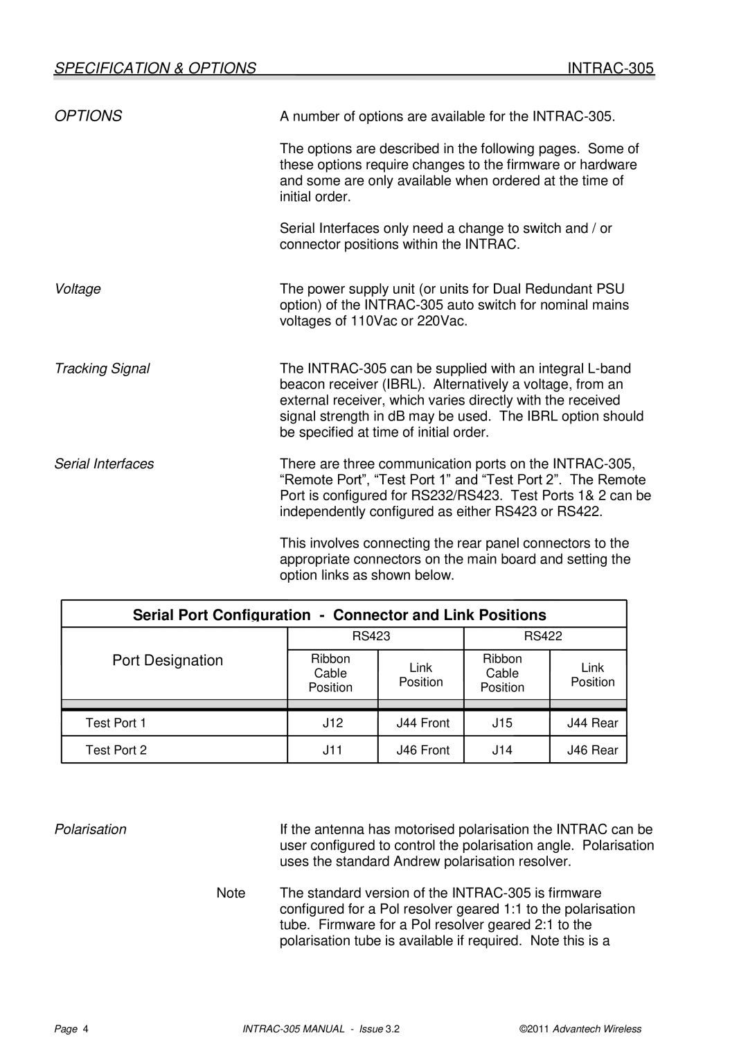
Serial Interfaces | There are three communication ports on the | |||||
|
| “Remote Port”, “Test Port 1” and “Test Port 2”. The Remote | ||||
|
| Port is configured for RS232/RS423. Test Ports 1& 2 can be | ||||
|
| independently configured as either RS423 or RS422. | ||||
|
| This involves connecting the rear panel connectors to the | ||||
|
| appropriate connectors on the main board and setting the | ||||
|
| option links as shown below. |
|
|
| |
| Serial Port Configuration - Connector and Link Positions |
|
| |||
|
| RS423 |
| RS422 |
|
|
| Port Designation | Ribbon | Link | Ribbon | Link | |
|
| Cable | Cable | |||
|
| Position | Position | |||
|
| Position | Position | |||
|
|
|
|
| ||
|
|
|
|
|
|
|
|
|
|
|
|
|
|
| Test Port 1 | J12 | J44 Front | J15 | J44 Rear | |
| Test Port 2 | J11 | J46 Front | J14 | J46 Rear | |
Polarisation | If the antenna has motorised polarisation the INTRAC can be |
| user configured to control the polarisation angle. Polarisation |
| uses the standard Andrew polarisation resolver. |
Note | The standard version of the |
| configured for a Pol resolver geared 1:1 to the polarisation |
| tube. Firmware for a Pol resolver geared 2:1 to the |
| polarisation tube is available if required. Note this is a |
Page 4 | ©2011 Advantech Wireless |