OPERATION |
|
Emergency Stop Button | Pressing the button removes all drive from the antenna. The |
| button locks in the safe position when pressed. To enable |
| drive to return to the antenna the button must be rotated |
| clockwise until it releases. |
On/Off Switch | Illuminated rocker switch to apply power to the |
| Illuminated when the INTRAC is on. On Dual Redundant |
| PSU units the rocker switch is replaced by status LEDs. |
Dual Redundant Status Leds | On Dual Redundant PSU units there is a green and red status |
| LED for each PSU. Green indicates that the PSU is powered |
| and working normally. Red indicates thjat the PSU is |
| powered but faulty. When the PSU is unpowered both LEDs |
| will be off. The INTRAC will operate correctly when at least 1 |
| green LED is illuminated. |
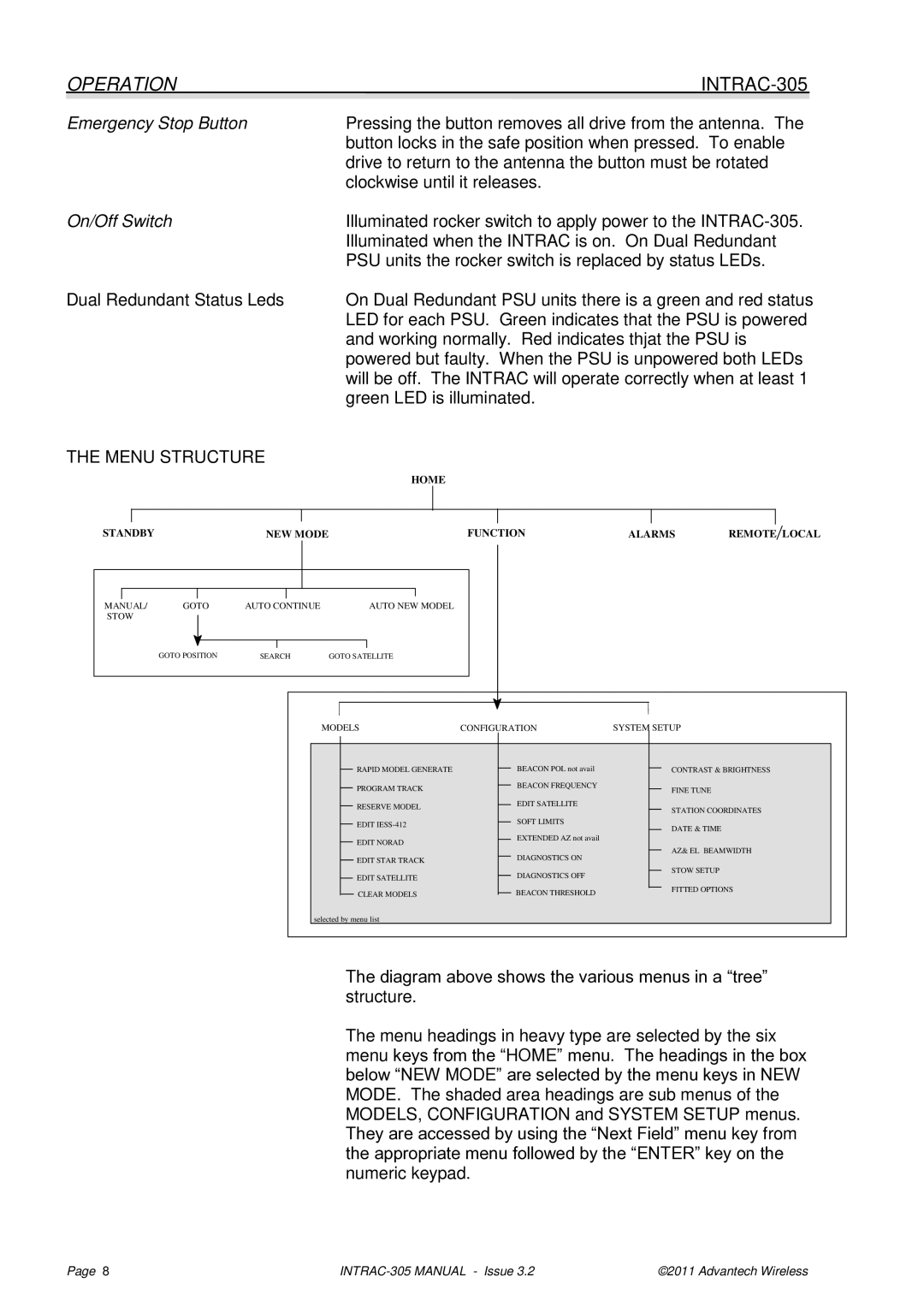
THE MENU STRUCTURE
HOME
STANDBY | NEW MODE | FUNCTION | ALARMS | REMOTE LOCAL |
MANUAL/ | GOTO | AUTO CONTINUE | AUTO NEW MODEL |
STOW |
|
|
|
| GOTO POSITION | SEARCH | GOTO SATELLITE |
MODELS | CONFIGURATION | SYSTEM | SETUP | |||||||
|
|
|
|
|
|
|
|
|
|
|
|
|
| RAPID MODEL GENERATE |
|
|
| BEACON POL not avail |
|
| CONTRAST & BRIGHTNESS |
|
|
|
|
|
| |||||
|
|
| PROGRAM TRACK |
|
|
| BEACON FREQUENCY |
|
| FINE TUNE |
|
|
|
|
|
|
| ||||
|
|
|
|
|
| EDIT SATELLITE |
|
| ||
|
|
| RESERVE MODEL |
|
|
|
|
| STATION COORDINATES | |
|
|
|
|
|
|
| ||||
|
|
| EDIT |
|
|
| SOFT LIMITS |
|
| |
|
|
|
|
|
|
|
| DATE & TIME | ||
|
|
|
|
|
|
| ||||
|
|
|
|
|
| EXTENDED AZ not avail |
|
| ||
|
|
| EDIT NORAD |
|
|
|
|
| ||
|
|
|
|
|
|
|
| AZ& EL BEAMWIDTH | ||
|
|
|
|
|
|
| ||||
|
|
|
|
|
| DIAGNOSTICS ON |
|
| ||
|
|
| EDIT STAR TRACK |
|
|
|
|
| ||
|
|
|
|
|
|
|
| |||
|
|
|
|
|
|
|
|
| ||
|
|
|
|
|
|
|
|
|
| |
|
|
| EDIT SATELLITE |
|
|
| DIAGNOSTICS OFF |
|
| STOW SETUP |
|
|
|
|
|
|
|
| |||
|
|
|
|
|
|
|
| FITTED OPTIONS | ||
|
|
|
|
|
| BEACON THRESHOLD |
|
| ||
|
|
| CLEAR MODELS |
|
|
|
|
| ||
|
|
|
|
|
|
|
| |||
|
|
|
|
|
|
|
|
| ||
selected by menu list
The diagram above shows the various menus in a “tree” structure.
The menu headings in heavy type are selected by the six menu keys from the “HOME” menu. The headings in the box below “NEW MODE” are selected by the menu keys in NEW MODE. The shaded area headings are sub menus of the MODELS, CONFIGURATION and SYSTEM SETUP menus. They are accessed by using the “Next Field” menu key from the appropriate menu followed by the “ENTER” key on the numeric keypad.
Page 8 | ©2011 Advantech Wireless |