6
|
|
| INSTALLATION | |||||
Test Port 1 & 2 RS423 |
|
|
|
|
|
| ||
|
|
|
|
|
|
|
| |
| INTRACTM 305 Serial Port Connector |
| Remote Control PC |
|
| |||
| 9 way D type |
| Signal Type | Signal Name | Signal Type | PC Connector |
|
|
| Socket |
|
|
|
| |||
|
|
|
|
|
|
|
|
|
| 1 |
| Passive | DCD |
|
|
|
|
| 2 |
| output | RXD | input |
|
|
|
| 3 |
| input | TXD | output |
|
|
|
| 4 |
|
|
|
|
|
|
|
| 5 |
| GND | GND | GND |
|
|
|
| 6 |
| Passive | DSR |
|
|
|
|
| 7 |
|
|
|
|
|
|
|
| 8 |
| Passive | CTS |
|
|
|
|
| 9 |
| N/C |
| N/C |
|
|
|
|
|
|
|
|
|
|
|
|
Test Port 1 & 2 RS422 |
|
|
|
|
|
| ||
|
|
|
| |||||
| INTRACTM 305 Serial Port Connector |
| Remote Control PC |
| ||||
| 9 way D type |
| Signal Type | Signal Name | Signal Type | PC Connector |
|
|
| Socket |
|
|
| ||||
|
|
|
|
|
|
|
|
|
| 1 |
|
|
|
|
|
|
|
| 2 |
| output | RXDB = RXD- | input |
|
|
|
| 3 |
| input | TXDB = TXD- | output |
|
|
|
| 4 |
|
|
|
|
|
|
|
| 5 |
| GND |
|
|
|
|
|
| 6 |
| output | RXDA = RXD+ | input |
|
|
|
| 7 |
| input | TXDA = TXD+ | output |
|
|
|
| 8 |
|
|
|
|
|
|
|
| 9 |
|
|
|
|
|
|
|
|
|
|
|
|
|
|
|
|
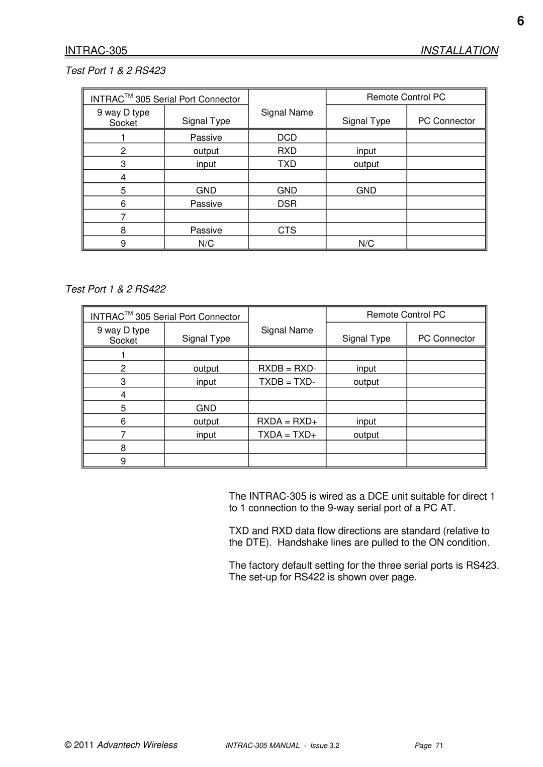
The
TXD and RXD data flow directions are standard (relative to the DTE). Handshake lines are pulled to the ON condition.
The factory default setting for the three serial ports is RS423.
The
© 2011 Advantech Wireless | Page 71 |
