INSTALLATION |
|
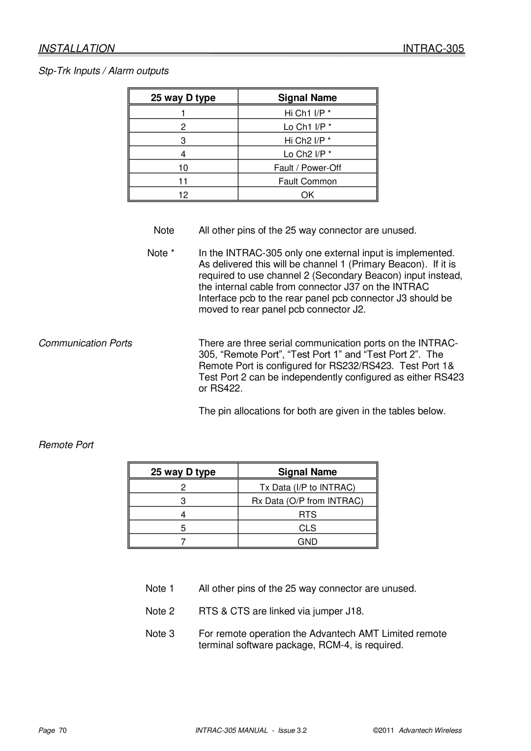
Stp-Trk Inputs / Alarm outputs
25 way D type | Signal Name |
|
|
1 | Hi Ch1 I/P * |
2 | Lo Ch1 I/P * |
3 | Hi Ch2 I/P * |
4 | Lo Ch2 I/P * |
10 | Fault / |
11 | Fault Common |
12 | OK |
|
|
| Note | All other pins of the 25 way connector are unused. | |||
| Note * | In the | |||
|
| As delivered this will be channel 1 (Primary Beacon). If it is | |||
|
| required to use channel 2 (Secondary Beacon) input instead, | |||
|
| the internal cable from connector J37 on the INTRAC | |||
|
| Interface pcb to the rear panel pcb connector J3 should be | |||
|
| moved to rear panel pcb connector J2. | |||
Communication Ports | There are three serial communication ports on the INTRAC- | ||||
|
| 305, “Remote Port”, “Test Port 1” and “Test Port 2”. The | |||
|
| Remote Port is configured for RS232/RS423. Test Port 1& | |||
|
| Test Port 2 can be independently configured as either RS423 | |||
|
| or RS422. |
|
| |
|
| The pin allocations for both are given in the tables below. | |||
Remote Port |
|
|
|
| |
|
|
|
|
| |
| 25 way D type |
| Signal Name |
| |
|
|
|
|
|
|
| 2 |
|
| Tx Data (I/P to INTRAC) |
|
| 3 |
|
| Rx Data (O/P from INTRAC) |
|
| 4 |
|
| RTS |
|
| 5 |
|
| CLS |
|
| 7 |
|
| GND |
|
|
|
|
|
| |
| Note 1 | All other pins of the 25 way connector are unused. | |||
| Note 2 | RTS & CTS are linked via jumper J18. | |||
| Note 3 | For remote operation the Advantech AMT Limited remote | |||
|
| terminal software package, | |||
Page 70 | ©2011 Advantech Wireless |