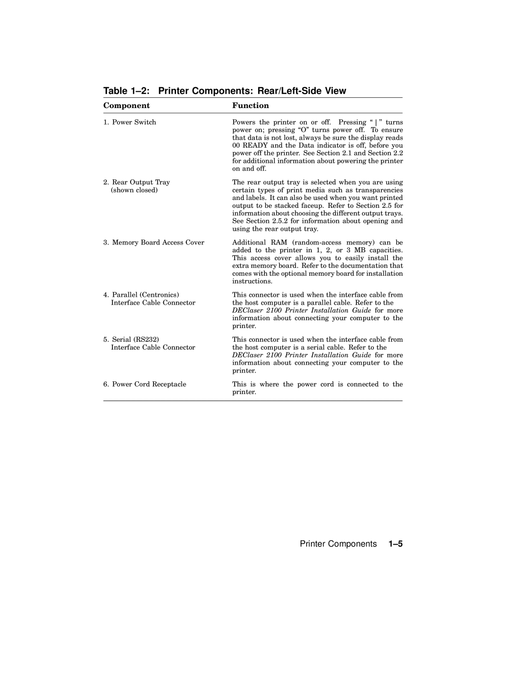
Table 1–2: Printer Components: Rear/Left-Side View
Component | Function |
1. Power Switch | Powers the printer on or off. Pressing `` '' turns |
| power on; pressing ``O'' turns power off. To ensure |
| that data is not lost, always be sure the display reads |
| 00 READY and the Data indicator is off, before you |
| power off the printer. See Section 2.1 and Section 2.2 |
| for additional information about powering the printer |
| on and off. |
2. Rear Output Tray | The rear output tray is selected when you are using |
(shown closed) | certain types of print media such as transparencies |
| and labels. It can also be used when you want printed |
| output to be stacked faceup. Refer to Section 2.5 for |
| information about choosing the different output trays. |
| See Section 2.5.2 for information about opening and |
| using the rear output tray. |
3. Memory Board Access Cover | Additional RAM |
| added to the printer in 1, 2, or 3 MB capacities. |
| This access cover allows you to easily install the |
| extra memory board. Refer to the documentation that |
| comes with the optional memory board for installation |
| instructions. |
4. Parallel (Centronics) | This connector is used when the interface cable from |
Interface Cable Connector | the host computer is a parallel cable. Refer to the |
| DEClaser 2100 Printer Installation Guide for more |
| information about connecting your computer to the |
| printer. |
5. Serial (RS232) | This connector is used when the interface cable from |
Interface Cable Connector | the host computer is a serial cable. Refer to the |
| DEClaser 2100 Printer Installation Guide for more |
| information about connecting your computer to the |
| printer. |
6. Power Cord Receptacle | This is where the power cord is connected to the |
| printer. |
|
|
