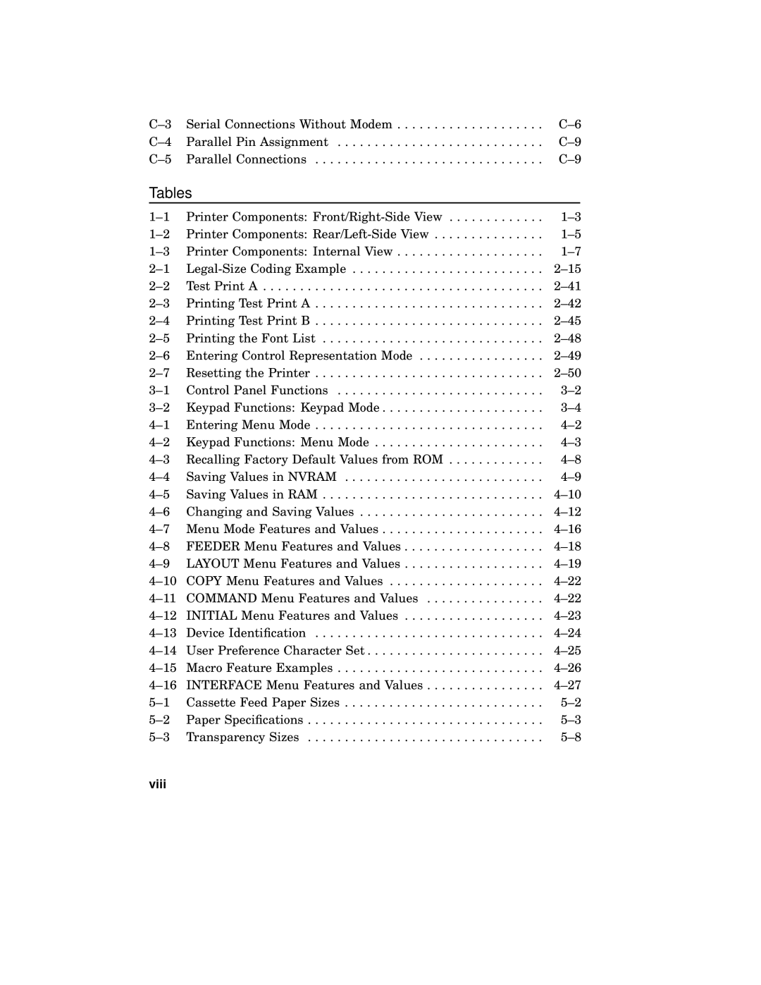
Serial Connections Without Modem | ||
Parallel Pin Assignment | ||
Parallel Connections |
Tables
Printer Components: | ||
Printer Components: | ||
Printer Components: Internal View | ||
Test Print A | ||
Printing Test Print A | ||
Printing Test Print B | ||
Printing the Font List | ||
Entering Control Representation Mode | ||
Resetting the Printer | ||
Control Panel Functions | ||
Keypad Functions: Keypad Mode | ||
Entering Menu Mode | ||
Keypad Functions: Menu Mode | ||
Recalling Factory Default Values from ROM | ||
Saving Values in NVRAM | ||
Saving Values in RAM | ||
Changing and Saving Values | ||
Menu Mode Features and Values | ||
FEEDER Menu Features and Values | ||
LAYOUT Menu Features and Values | ||
COPY Menu Features and Values | ||
COMMAND Menu Features and Values | ||
INITIAL Menu Features and Values | ||
Device Identification | ||
User Preference Character Set | ||
Macro Feature Examples | ||
INTERFACE Menu Features and Values | ||
Cassette Feed Paper Sizes | ||
Paper Specifications | ||
Transparency Sizes |
