|
|
|
|
|
|
|
|
| 2268 |
PWR100R |
|
| DC |
|
AT- |
|
| OUT | |
|
| F | ||
VAC~ 2A | AULT | |||
|
| MAX |
| |
|
|
|
| |
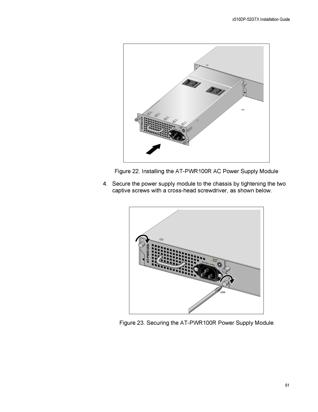
Figure 22. Installing the AT-PWR100R AC Power Supply Module
4.Secure the power supply module to the chassis by tightening the two captive screws with a cross-head screwdriver, as shown below.
PWR100R |
|
| DC |
|
AT- |
|
| OUT | |
|
| F | ||
100- |
| AULT | ||
| 240VA | C~ 2A | MAX |
|
|
|
|
| |
|
|
|
| 2269 |
Figure 23. Securing the AT-PWR100R Power Supply Module
61