x510DP-52GTX Installation Guide
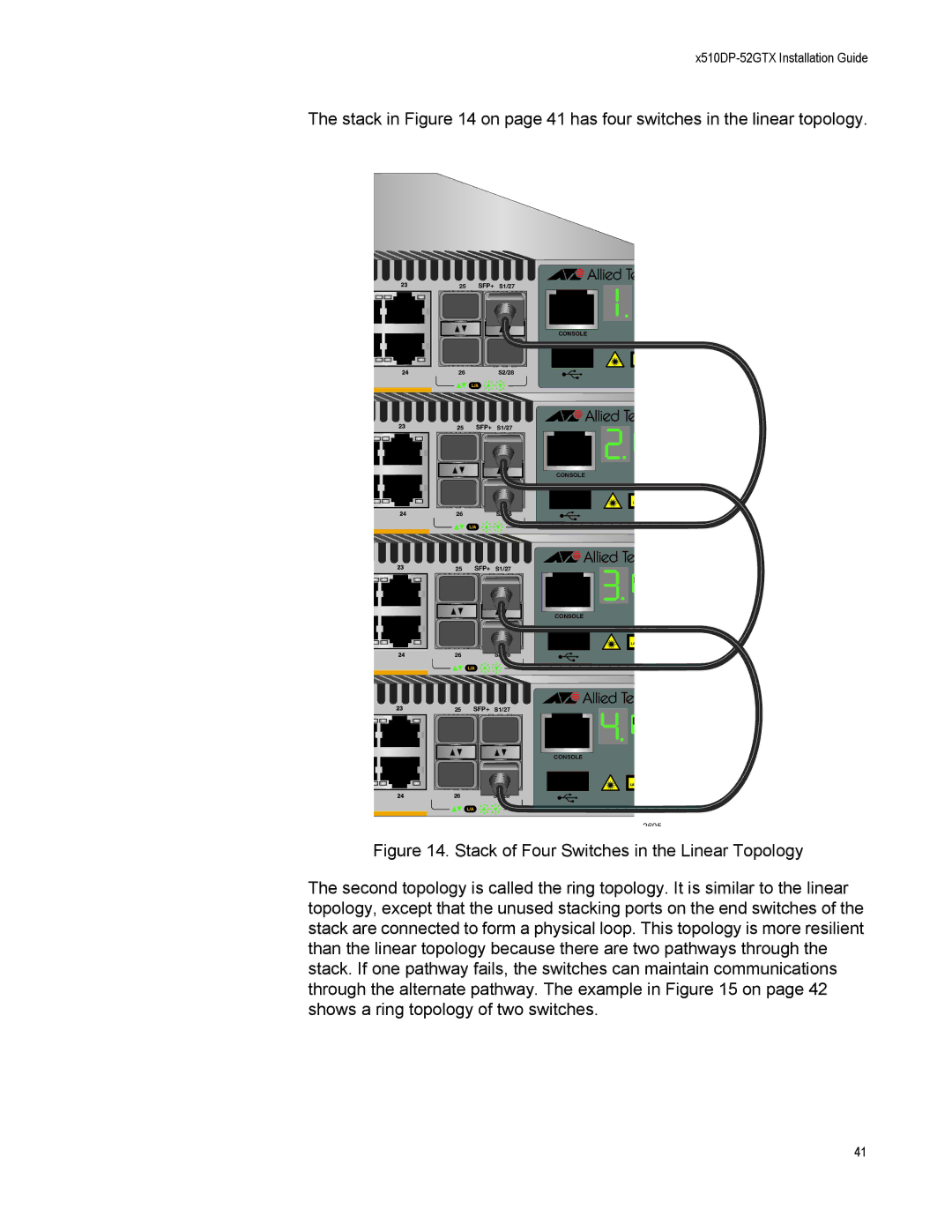
The stack in Figure 14 on page 41 has four switches in the linear topology.
25 SFP+ S1/27
CONSOLE
26 S2/28
25 SFP+ S1/27
CONSOLE
26 S2/28
25 SFP+ S1/27
CONSOLE
26
S2/28
25 SFP+ S1/27
CONSOLE
26
S2/28
2695
Figure 14. Stack of Four Switches in the Linear Topology
The second topology is called the ring topology. It is similar to the linear topology, except that the unused stacking ports on the end switches of the stack are connected to form a physical loop. This topology is more resilient than the linear topology because there are two pathways through the stack. If one pathway fails, the switches can maintain communications through the alternate pathway. The example in Figure 15 on page 42 shows a ring topology of two switches.
41
