Chapter 9: Cabling the Networking Ports
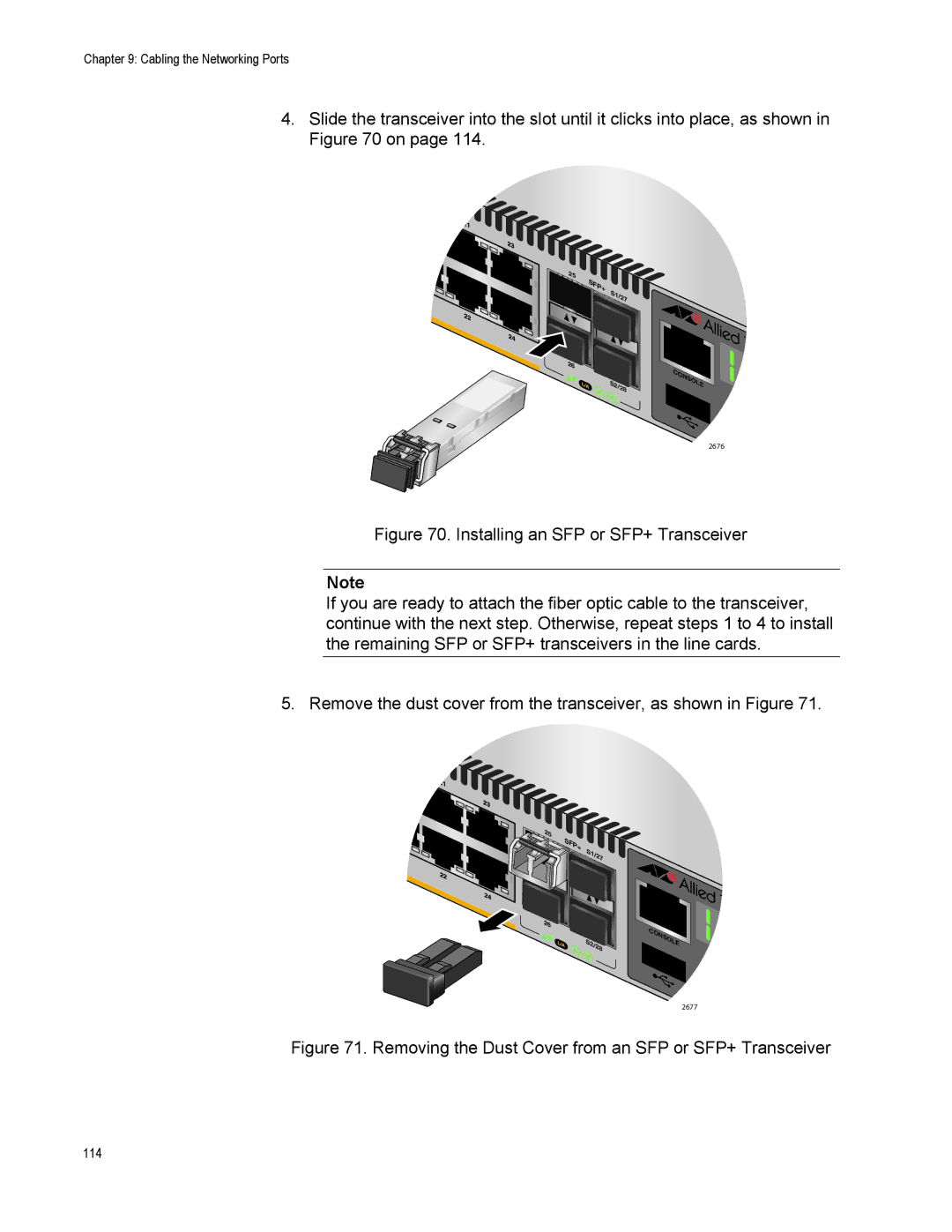
4.Slide the transceiver into the slot until it clicks into place, as shown in Figure 70 on page 114.
25 |
|
|
|
|
SFP+ | S1 | /27 |
| |
|
| |||
|
|
| ||
26 |
|
|
|
|
| S2 | /2 |
| SO |
| 8 |
| ||
|
|
| ||
2676
Figure 70. Installing an SFP or SFP+ Transceiver
Note
If you are ready to attach the fiber optic cable to the transceiver, continue with the next step. Otherwise, repeat steps 1 to 4 to install the remaining SFP or SFP+ transceivers in the line cards.
5. Remove the dust cover from the transceiver, as shown in Figure 71.
![]()
![]() 25
25
![]() SFP+
SFP+
![]() S1
S1
![]()
![]() 26
26 ![]()
S2/2 | 8 | LE |
2677
Figure 71. Removing the Dust Cover from an SFP or SFP+ Transceiver
114