Chapter 4: Installing the Switch and its Power Supplies
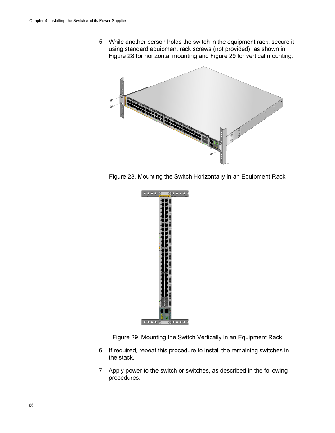
5.While another person holds the switch in the equipment rack, secure it using standard equipment rack screws (not provided), as shown in Figure 28 for horizontal mounting and Figure 29 for vertical mounting.
![]()
![]()
![]()
![]()
![]() x510DP-52GTX
x510DP-52GTX![]()
![]()
1 |
|
| 3 |
| 5 |
| 7 |
| 9 |
2 | 11 |
| 4 |
| 13 |
| 6 |
| 15 |
| 8 |
| 17 |
| 10 |
| 19 |
| 12 |
| 14 |
| 16 |
| 18 |
| 20 |
| 1000 LINK |
ACT
21
22![]()
10/100 LINK
23
24
ACT
25 ![]()
![]()
![]()
![]()
![]() 26
26
FDX
27 ![]()
![]()
![]()
28![]()
HDX
COL
29 |
| |
31 |
| |
33 |
| |
35 |
| |
37 |
| |
30 |
| |
39 |
| |
32 |
| |
41 |
| |
34 | 43 | |
36 | ||
45 | ||
38 | 47 | |
40 |
| |
42 | 25 | |
| 44 | |
| 46 | |
| 48 | |
| 26 |
SFP+
S1/27 |
|
S2/28 | CONSOLE |
2674
Figure 28. Mounting the Switch Horizontally in an Equipment Rack
| 2 | 1 |
|
| |||
| 4 | 3 |
|
| |||
| 6 | 5 |
|
| |||
| 8 | 7 |
|
| |||
| 10 | 9 |
|
| |||
| 12 | 11 |
|
| |||
| 14 | 13 |
|
| |||
| 16 | 15 |
|
| |||
| 18 | 17 |
|
| |||
| 20 | 19 |
|
| |||
| 22 | 21 |
|
| |||
| 24 | 23 |
|
| |||
| 26 | 25 |
|
| |||
| 28 | 27 |
|
| |||
| 30 | 29 |
|
| |||
| 32 | 31 |
|
| |||
| 34 | 33 |
|
| |||
| 36 | 35 |
|
| |||
| 38 | 37 |
|
| |||
| 40 | 39 |
|
| |||
| 42 | 41 |
|
| |||
| 44 | 43 |
|
| |||
| 46 | 45 |
|
| |||
| 48 | 47 |
|
| |||
| 50 |
|
|
| 49 |
|
|
|
|
|
|
|
| ||
| S2/52 |
|
|
| SFP+ |
|
|
|
|
|
|
|
| ||
|
|
|
| S1/51 |
|
| |
|
|
| CONSOLE |
|
|
|
|
|
|
|
|
|
|
| |
|
|
|
|
|
|
|
|
|
|
|
|
|
|
|
|
|
|
|
|
|
|
|
|
|
|
|
|
|
|
|
|
|
|
|
|
|
|
|
|
Figure 29. Mounting the Switch Vertically in an Equipment Rack
6.If required, repeat this procedure to install the remaining switches in the stack.
7.Apply power to the switch or switches, as described in the following
procedures.
66