Take Apart | Screw Matrix - 2 | |
|
|
|
|
|
|
|
|
| Scale = 1 inch |
|
|
| |||||||||||||||
0 | 1 | 1 | 3 | 1 | 5 | 3 |
|
|
|
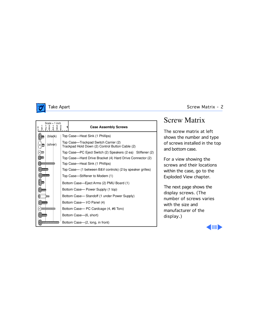
| 1 | Case Assembly Screws | ||||||||||||
8 |
|
| 4 | 8 | 2 | 8 | 4 |
|
|
|
| |||||||||||||
|
|
|
|
|
|
|
|
|
|
|
|
|
|
|
|
|
|
|
|
|
|
|
|
|
(black) Top |
| ||
(silver) | Top |
| |
Trackpad Hold Down (2) Control Button Cable (2) | |||
| |||
| Top | Stiffener (2) | |
| Top | ||
| Top |
| |
| Top Case— (1 between B&V controls) (2 by speaker grilles) | ||
| Top |
| |
| Bottom |
| |
| Bottom Case— Power Supply (1 top) |
| |
| Bottom Case— Standoff (1 under Power Supply) |
| |
| Bottom Case— I/O Panel (4) |
| |
| Bottom Case— PC Cardcage (4, #6 Torx) |
| |
| Bottom |
| |
| Bottom |
| |
Screw Matrix
The screw matrix at left shows the number and type of screws installed in the top and bottom case.
For a view showing the screws and their locations within the case, go to the Exploded View chapter.
The next page shows the display screws. (The number of screws varies with the size and manufacturer of the display.)